
Ducati Diavel Service Manual: Renewal of the headlight
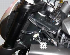
Disconnect the headlight connectors (a) from the main wiring (refer to the tables of paragraph "routing of wiring on frame", sect. 6 - 1).
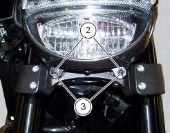
Loosen nuts (2) that fix the front optical unit to the bottom yoke, and recover the washers (3).

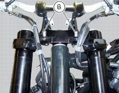
Remove the complete front optical unit by sliding it upwards and releasing it from pins (b) of the supporting bracket.

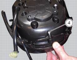
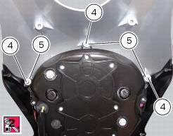
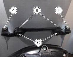
Release the headlight from the front optical unit support by loosening the screws (4) and recovering the washers (5).
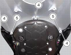
Refit the headlight on the front optical unit support, insert the spacers with collars (5) and the screws (4).
Apply the recommended threadlocker to the screws (4).
Tighten the screws (4) to a torque of 6 nm +/- 10% (sect. 3 - 3, Frame torque settings).

Check for the pads (6) on the supporting bracket.
Apply the recommended threadlocker to the screws (4).
Tighten the screws (4) to a torque of 6 nm +/- 10% (sect. 3 - 3, Frame torque settings).
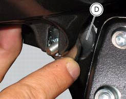
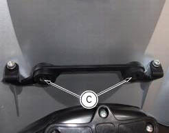
Refit the front optical unit by placing its lower part on the pads (d) and inserting the pins (b) into the eyelets (c) of the supporting bracket.
Fix the front optical applying a torque of 10 nm +/- 10% (sect. 3 - 3, Frame torque settings) to the nuts (2) with washers (3).
Reconnect the headlight connectors (a) to the main wiring (refer to the tables of paragraph "routing of wiring on frame", sect. 6 - 1).


 Changing bulbs
Changing the headlight bulbs
Before replacing a burnt out light bulb, ensure that the replacement bulb has
the same voltage and power rating as
specified for the lighting device in question (sect. ...
Other materials:
Operations to be carried out by the dealer
List of operations to be performed at 1000 km
Reading of the error memory with dds on the engine control units,
vehicle and abs
Change the engine oil
Change the engine oil filter
Check the indicators and lighting
Check the safety devices (side ...
Ground connection locations
The negative cable, which is normally connected to the negative pole of the
battery, is fastened to the crankcase. From here, the cable
branches off and splits up within the electrical system to carry the ground
connection to the different elements in the system.
The image shows the ground ...
Riding mode customisation
This function customises each riding style.
To access the function it is necessary to view the "setting"
menu page 48, using button (1, fig. 14) ?
or (2, fig. 14)
? select the "riding mode" function
and press the
reset button (12, fig. 12) To go to next page.
W ...