
Ducati Diavel Service Manual: Refitting the front footrests
Note
The assembly of the front footrests is described only for the right one (2) but it is the same also for the left one.
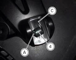
Place the spring (4) bringing the end (a) onto the footrest (2).
Place the footrest (2) in the correct position, by inserting the end (c) of the spring (4) in the hole (d) of the frame plate.
Apply the recommended grease to the pin (3).
Insert pin (3) orienting it as illustrated.
Lock the pin by inserting the circlip (5).
 Removal of the front footrests
Note
The removal of the front footrests is described only for the right one (2)
but it is the same also for the left one.
Remove the circlip (5) by releasing the pin (3).
Slide the pin (3) off ...
 Removing the front footrest brackets
Note
The assembly of the front footrests is described only for the right one
(2) but it is the same also for the left one.
Place the spring (4) bringing the end (a) onto the footrest (2).
Place ...
Other materials:
Appropriate diagnosis tools
97900.0211 Dds (ducati diagnosis system) without cables
97900.0227 Power cable and diagnosis
97900.0222 Power cable and diagnosis 1060838 (measurement module)
97900.0218 Vacuum sensor
552.1.039.1A Pressure sensor
97900.0220 Pressure/vacuum tube
97900.0221 Union
...
Background setting function for the dashboard on tank - dashboard 1
This function allows setting the "background" of the dashboard on tank.
To access the function it is necessary to view the ""setting" menu", using
buttons (1) "s" or (2) "t" select the "back
light" function and press the reset button (3) to enter the following page.
Use button (1) "s" or (2 ...
Indicator trip time - trip time
This function shows the vehicle trip time.
The calculation is made considering the time travelled since
the last trip 1 reset. When trip 1 is reset, the value is set to
zero.
The active phase calculation occurs when the engine is
running and the vehicle is stopped (when the vehicle is not
...