
Ducati Diavel Service Manual: Symbols - abbreviations - references
To allow quick and easy consultation, this manual uses graphic symbols to highlight situations in which maximum care is required, as well as practical advice or information. Pay attention to the meaning of the symbols since they serve to avoid repeating technical concepts or safety warnings throughout the text. The symbols should therefore be seen as an aid to memory. Please refer to this page whenever in doubt as to their meaning.
The terms right-hand and left-hand refer to the motorcycle viewed from the riding position.
Warning
Failure to comply with these instructions may put you at risk, and could lead to severe injury or even death.
Important
Failure to follow the instructions in text marked with this symbol can lead to serious damage to the motorcycle and its components.
Note
This symbol indicates additional useful information for the current operation.
Text references
References in bold type indicate a part that is not illustrated in the figures next to the text, but which can be found in the exploded views at the beginning of each chapter.
References in non-bold type indicate a part that is illustrated in the figures alongside the text.
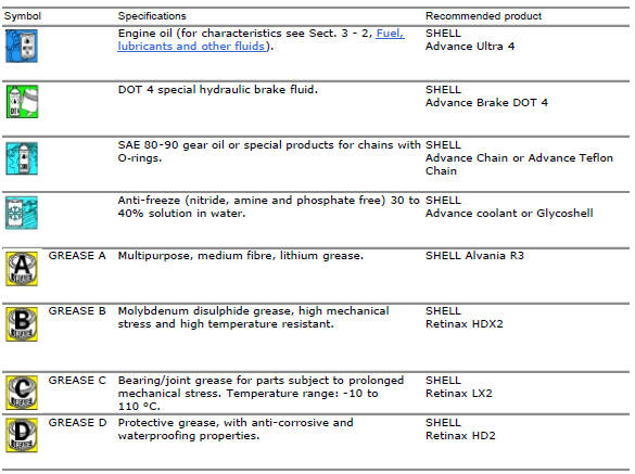
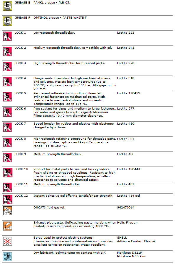
Product specifications
Symbols in the diagram show the type of threadlocker, sealant or lubricant to be used at the points indicated. The table below shows the symbols used and the specifications of the various products.

 How to use this manual
How to use this manual
This manual has been prepared for technical personnel at ducati authorized
service centres with the aim of providing
fundamental information on how to work in accordance wit ...

Other materials:
Warranty
In your own interest, and in order to guarantee product
reliability, you are strongly advised to refer to a ducati dealer
or authorised service centre for servicing that requires any
particular technical expertise.
Our highly skilled staff have the tools required to perform any
servicing job ...
Removal of the front mudguard
Undo the screw (7) and remove the front brake lines (a) from the hose grommet
(4).
Undo and remove the special retaining screws (5): keep the spacers (6).
Remove the front mudguard (1).
Warning
The version provided with carbon mudguards features nylon washers
instead of the spacers (6) ...
Filling the clutch circuit
Warning
Clutch fluid will damage painted surfaces if spilled on them. It is
also very harmful if it comes into contact with the skin or
with the eyes; in the case of accidental contact, wash the affected area
thoroughly with plenty of running water.
Remove cover (1) and membrane from the clut ...