Ducati Diavel Service Manual: Abs disabled information not displayed
Fault codes
Dds: displays a fault code described in the description of the abs system.
Dashboard: no fault code displayed.
Wiring diagram

Checks
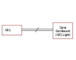
The abs fault indicator indicates the occurrence of one or more faults in the antilock brake system, or if the system itself has been disabled by the rider, using the relative control. The signal causing activation of the abs fault indicator when the antilock brake system is disabled, comes directly from the abs unit, and the information is transmitted over the can line by the bbs unit, so that it may be acquired by the dashboard, where the indicator itself is located.
Diagnose the abs unit.
Check the integrity of the electrical circuit and connections (short circuits to ground, short circuits to vdc, open circuits).
If the above test did not identify the problem, contact ducati.
Note
Check integrity of electric circuit - short-circuit to vdc = with dashboard on, using a voltmeter, a voltage is measured between the wire tested and ground.
Check integrity of electric circuit - short-circuit to ground = with the battery cables disconnected, using an ohmmeter, continuity is detected between the wire tested and ground.
Check integrity of electric circuit - open circuit = with the battery cables disconnected, using an ohmmeter, no continuity is detected between the two ends of the wire tested.
 Abs fault indicator not working
Fault codes
Dds: displays a fault code described in the description of the abs system.
Dashboard: no fault code displayed.
Wiring diagram
Checks
The abs fault indicator indicates the occurr ...
 Stop light not working
Fault codes
Dds: stop light diagnosis -> stop light error (generic stop light malfunction
indication).
Dashboard: the error "stop light" is shown on the service display. The eobd
warning li ...
Other materials:
Stored lap erase function
This function erases the stored laps.
To access the function it is necessary to view the "setting" menu page 48, using
button (1, fig. 14) ?"" or (2, fig.
14) ?"" select the "lap" function and
press the reset button
(12, fig. 12) To go to next page.
...
Camshafts
Head
Stud bolt
Special screw
Sealing washer
Horizontal cylinder head cover
Vertical cylinder head cover
Special screw
O-ring
Head gasket
Screw
Pin
Union
Clamp
Horizontal cylinder exhaust camshaft
Horizontal cylinder intake camshaft
Plug
Sealing ring
Vertical ...
Turn indicators (automatic reset)
The instrument panel controls the automatic reset of the turn
indicators.
After activating one of the two turn indicators, they can be
deactivated using the reset button (12, fig. 12).
If the turn indicator is not "reset" manually, the instrument
panel will automatically switch it ...