
Ducati Diavel Service Manual: Stop light not working
Fault codes
Dds: stop light diagnosis -> stop light error (generic stop light malfunction indication).
Dashboard: the error "stop light" is shown on the service display. The eobd warning light activates.
Wiring diagram
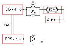
Db dashboard connection, bbs bbs unit connection, a front brake button, p rear brake button, l stop light. A key on power (+15 from hands free relay 30), db 4 grey/red - gr/r, the switch cable connected to a via the fuse is black - bk, bbs 6 grey/red - gr/r, ground on stop light, black - bk.
Location of connections and components
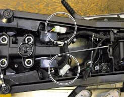
Rear running light and stop light connection.
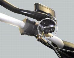
Front brake button mounted near lever operating brake pump.
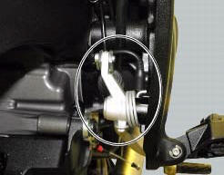
Rear brake button mounted near lever operating brake pump. The button is normally closed (when the brake lever does not press on the button because it has been pressed by enough to cause a braking effect, the contacts close, short circuiting the contacts).
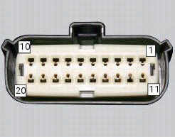
Pin numbering for wiring harness side dashboard connector.
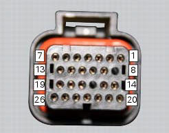
Pin numbering of wiring harness side bbs unit connection.
 Abs disabled information not displayed
Fault codes
Dds: displays a fault code described in the description of the abs system.
Dashboard: no fault code displayed.
Wiring diagram
Checks
The abs fault indicator indicates the occurr ...
 Exhaust by-pass valve not working correctly
Fault codes
Dds: exvl diagnosis -> position error, potentiometer, short circuit to ground
or open circuit (s.C. Gnd or c.O.),
Potentiometer short circuited to vdc (potentiometer s.C vdc).
Da ...
Other materials:
Units of measurement modification function
This function allows you to change the units of measurement
of the displayed values.
To access the function it is necessary to view the "setting" menu page 48, using
button (1, fig. 14) ?"" or (2, fig.
14) ?" " select the "set units" function
and pre ...
California emission control warranty statement
Your warranty rights and obligations
The california air resources board is pleased to explain the
emission control system warranty on your my 2011
motorcycle. In california, new motor vehicles must be
designated, built and equipped to meet the state's stringent
anti-smog standards. Ducati north ...
Trip 2 meter
This function shows the distance travelled since the trip meter was last
reset (in km or miles depending on the specific
application).
Press and hold (1) "s" for 3 seconds while in this function to reset the trip
odometer.
When the reading exceeds 9999.9, Distance travelled is reset and t ...