
Ducati Diavel Service Manual: Adjusting of the air-gap phonic wheel sensor
(For front as well as rear sensor) in each case of maintenance that foresees:
- Replacement or refitting of the wheel
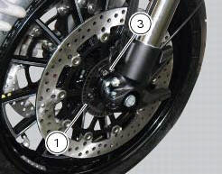
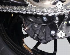
- Replacement or refitting of the phonic wheel (1) or (2)
- Replacement or refitting of the brake discs
- Replacement or refitting of the speed sensor (3) or (4)
- (Front) replacement or refitting of the sensor holder bracket
- (Rear) replacement or refitting of the calliper holder bracket
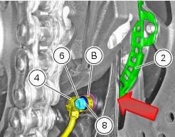
It is necessary to check the air-gap between the speed sensor and the phonic wheel, once the components are refitted.
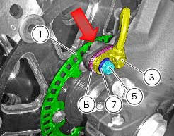
Place the appropriate number of shims (b) under the abs sensor so as to achieve 1.3 To 1.9 Mm air-gap between abs sensor and phonic wheel. When shimming is correct, a 1.3 Mm feeler gauge will fit between abs sensor and phonic wheel, whereas a 1.9 Mm will not.
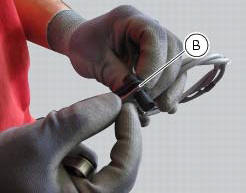
Check at three equally spaced locations (spaced about 120 apart) of the phonic wheels (1) and (2). Shims (b) come in two sizes: 0.2 Mm and 0.5 Mm. Combine the shims as required to achieve correct shimming.
When checking with the 1.3 Mm feeler gauge (go gauge) and the 1.9 Mm feeler gauge (no-go gauge), the abs sensors (3) and (4) must be firmly secured in their seats. This means you need to loosen and retighten the sensor retaining screw fully home with its washer each time you add or remove any shims.
Warning
For the front wheel abs sensor (3), total shims used must never exceed 3 mm on the base version and 3.7 Mm on the carbon version.
For the rear wheel abs sensor (4), total shims used must never exceed 3 mm.
After shimming, tighten the retaining screws (5) and (6) of the sensors (3) or (4) to a torque of 10 nm +/- 10% (sect. 3 - 3, Frame torque settings) placing washers (7) and (8) in-between and check again using the 1.3 Mm feeler gauge (go gauge) and the 1.9 Mm feeler gauge (no-go gauge).
Phonic wheels cleaning
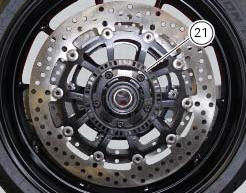
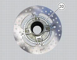
It is important to check that both phonic wheels (21) and (20) are always clean.
Otherwise: gently remove any possible dirt deposits with a cloth or metal brush. Avoid using solvents, abrasives and air or water jets directly on the phonic wheel (21) or (20).

 Bleeding of the abs hydraulic system
If some "sponginess" is detected on the brake control, due to air bubbles in
the system, bleed the system, as indicated in
sect. 4 - 3, Changing the brake fluid.
Before bleeding a brake pump, mo ...
Other materials:
Removal of the clutch
Note
For clarity, the figures show the engine removed from the frame.
Undo the fixing screws (1) and remove the ring (2) and the springs (3) from
the pressure plate (4).
Slide the pressure plate (4) paying attention to the circlips (6).
Remove the clutch control pin (14) and the ...
Disassembly of the rear brake control
The brake master cylinder is supplied only as a complete unit; internal
components cannot be replaced.
To disassemble the master cylinder's outer parts, follow the indications given
in the exploded view at the beginning of this
section.
If the bush (10) inside the brake pedal (6) needs to ...
Reassembling the clutch
Position the spacer (13).
Fit the flat ring (11) and the belleville washer (10) on the clutch center
(12), so that the convex side faces the clutch
drum.
Locate the belleville washer (8).
Apply the prescribed grease to the thread of the gearbox primary shaft and
the mating surfac ...