
Ducati Diavel Service Manual: Refitting the front brake system
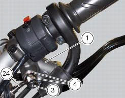
While refitting the system, pay special attention to the orientation of the pipe couplings (24) on the pump and the pipes (13) and (20) on the callipers (9) and (18).
Warning
If incorrectly positioned, the hose can affect brake operation and foul moving parts. Position the hose as shown in the figure.
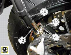
When reconnecting the brake hose to the calliper or master cylinder, make sure to install the sealing washers (4) either side of the hose end fitting.
After having oriented the pipe fitting (24) tighten the screw (3) to a torque of 23 nm +/- 10% (sect. 3 - 3, Frame torque settings).
After having oriented the pipes (13) and (20) in the front brake callipers (18) and (9) tighten the special screws (19) and (25) to a torque of 23 nm +/- 10% (sect. 3 - 3, Frame torque settings).
Note
Make sure that internal pipe fitting (13) and the external pipe fitting (20) are installed in the left brake calliper (9).
Fit the left calliper (9) over the disk.
Apply the recommended grease to the screws (21).
Hand tighten the screws (21) to secure the callipers to the fork legs.
Operate the brake lever two or three times until the circuit is pressurised and force the pads against the brake disc.
Repeat the operation for the right brake calliper (18).
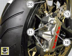

Hold the lever pulled towards the twistgrip and tighten the calliper screws (21) to the torque of 45 nm +/- 5% (sect. 3 - 3, Frame torque settings).
Insert brake rubber block (d) into grommet (b) and ensure it is centred.
Fold hose clip (b) and fasten it by starting the screw (c) in its thread.
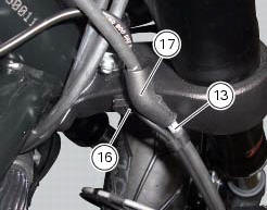
Insert hose (13) in bracket (17) and tighten screw (16) to a torque of 8 nm +/- 10% (sect. 3 - 3, Frame torque settings).
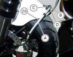
For correct position of the ties fastening the abs sensor cable (a) to front brake lines (20), please refer to sect. 7 - 6, Flexible wiring/hoses positioning.
 Refitting the brake disks
Before refitting the brake disc to the wheel, clean all contact surfaces
thoroughly and smear a medium strength
threadlocker on the threads of retaining screws (5).
Operating on the left side, f ...
 Rear brake
Rear speed sensor (abs)
Screw
Washer
Spring
Brake switch (rear)
Brake lever (rear)
Rear pump - control unit pipe
Sealing washer
Pin
Bush
O-ring
Screw
screw
Rear brake ...
Other materials:
Removing the electrical components support
Remove the following elements located inside the electrical components
support:
The battery fixing bracket (4) and the battery (14) as specified under
section 6 - 2, battery;
The voltage regulator (3) as specified under section 6 -
2,rectifier-regulator;
The solenoid starter (18) ...
Carrying the maximum load allowed
Your motorcycle is designed for travelling over long
distances with a full load in complete safety.
Even weight distribution is critical to preserving these safety
features and avoiding trouble when performing sudden
manoeuvres or riding on bumpy roads.
Warning
Do not exceed the total permi ...
Operating principle
The ducati abs brake system manages the front and rear brakes separately. A
pulse generator (phonic wheel), with a
ring of slots, is fixed onto each wheel. On the left calliper mounting bracket
of the front fork and on the rear brake calliper
holder plate are hall effect sensors which detect t ...