
Ducati Diavel Service Manual: Appropriate diagnosis tools
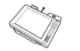
97900.0211 Dds (ducati diagnosis system) without cables
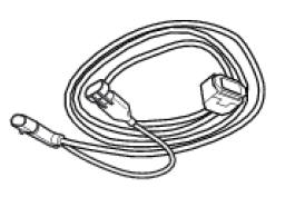
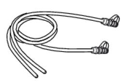
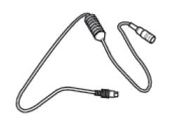
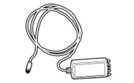
97900.0227 Power cable and diagnosis
97900.0222 Power cable and diagnosis 1060838 (measurement module)
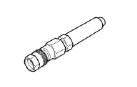
97900.0218 Vacuum sensor
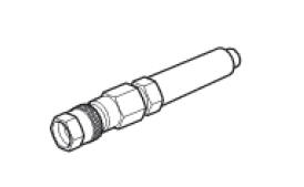
552.1.039.1A Pressure sensor
97900.0220 Pressure/vacuum tube
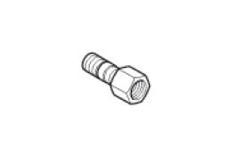
97900.0221 Union
97900.0228 Battery socket adapter
814.1.114.1A Oil pressure coupling
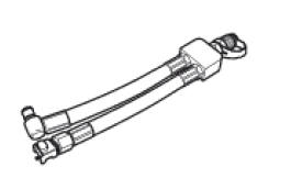
514.1.032.1A Auxiliary test cable
552.1.038.1A Cylinder compression cable m10 fitting

875.1.065.1A Oil pressure tube
97900.0230 Feeder
97900.0224 Feeder
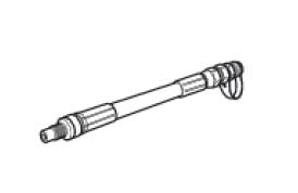
88765.1371 Belt tensioning sensor
88765.1374 Belt tensioning sensor bracket
590.1.189.1A Fuel pressure tube
88765.1126 Clamp-type amperemeter
97900.0227S Can network diagnosis cable
 Specific tools for the frame
88713.1072 Drift to install half bearing in bottom yoke
88713.2562 Chain assembly tool
88713.1058 Wrench for steering shaft nut
88713.1062 Tool for installing steering head bearings ...

Other materials:
Carrying the maximum load allowed
Your motorcycle is designed for travelling over long
distances with a full load in complete safety.
Even weight distribution is critical to preserving these safety
features and avoiding trouble when performing sudden
manoeuvres or riding on bumpy roads.
Warning
Do not exceed the total permi ...
Storing the bike away
If the motorcycle is to be left unridden over long periods, it is
advisable to carry out the following operations before storing
it away:
clean the motorcycle;
empty the fuel tank;
pour a few drops of engine oil into the cylinders through the
spark plug bores, then turn the engine over by hand ...
Removal of the licence plate holder
Disconnect connector (5) of the number plate holder wiring from the main one.
Release the number plate holder light cable from the ties and the cable grommets
as indicated in sect- 7 - 6, flexible
wiring/hoses positioning, since the cable is together with the rear abs sensor
cable.
...