
Ducati Diavel Owners Manual: Dtc (ducati traction control) setting function
This function allows you to customise the level of dtc intervention (ducati traction control) or disable it for every riding mode.
To access the function it is necessary to view the "setting" menu page 48, using
button (1, fig. 14) ?" " or (2, fig.
14) ?"  " select the "riding mode"
function and press the reset button (12, fig. 12) To go to next page. Use button
(1, fig. 14) ?" " or (2, fig. 14) ?"
 "
"
to select the riding style to
change and press the reset button (12, fig. 12).
To go to next page use button (1, fig. 14) ?" "
"
or (2, fig. 14) ?" " to select the "dtc" indication
and press the reset
button again (12, fig. 12) To confirm selection.
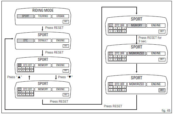
When accessing the function, the currently set dtc level appears at the
left-hand side of the display, inside a rectangle (ex.: Dtc 1). Use button (1,
fig. 14) ?" " or (2, fig. 14) ?"
 " to
" to
select the new intervention level (1 to 8) or off to disable
the traction control; after selecting the new setting, press
the reset button (12, fig. 12) To highlight "memory"
indication. At this point, store the new setting by pressing
and holding the reset button (12, fig. 12) For 3 seconds with
"memory" displayed. If the setting has been stored
successfully, the display will show "memorized" in green
for 2 seconds and the exit option will be highlighted
automatically.
To exit the setting function, press the reset button (12, fig.
12) Where "exit" is highlighted.
The dtc intervention increases, passing from level 1 to level 8.
The following table indicates the most suitable level of dtc
intervention for the various riding types as well as the default
settings in the "riding mode" that can be selected by the
rider: 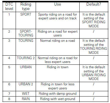
 Riding mode customisation
This function customises each riding style.
To access the function it is necessary to view the "setting"
menu page 48, using button (1, fig. 14) ?
or (2, fig. 14)
? select the & ...
 Tips on how to select the sensitivity level
Warning
The 8 level settings of the dtc were calibrated using
tyres of the same make, model and size as those originally
fitted to the motorcycle.
The use of tyres of different size to the orig ...
Other materials:
Clock setting function
This function sets the clock.
To access the function it is necessary to view the "setting" menu page 48, using
button (1, fig. 14) ?"
"or (2, fig. 14) ?""select the "clock"function and
press the reset button
(12, fig. 12) To confirm.
In the follow ...
Default function (resetting ducati default parameters)
This function resets the parameters set by ducati for each
riding style.
To access the function it is necessary to view the "setting" menu page 48, using
button (1, fig. 14) ?"
" or (2, fig. 14) ?" " select the "riding mode"
function and press the
r ...
Overhauling the front wheel
Wheel bearings
Before checking the dimensions, check the wear on wheel bearings. Check for
wear by hand after cleaning and degreasing
the bearings in their seats.
Turn the inner race.
Check the amount of radial and axial play. Excessive play will cause vibration
and make the bike unstabl ...