
Ducati Diavel Service Manual: Checking valve lift
Set the engine to the configuration described for the "checking and adjusting the valve clearances", previously indicated.
Position the tool 88765.1518 On the cylinder head: the part marked "a" should be on the intake side and the part marked "s" should be on the exhaust side.
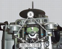
Seat the plate (a) and tighten the screws (b).
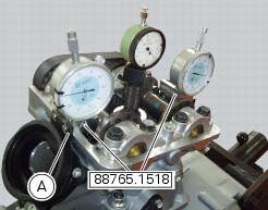
Set the opening valve clearance to zero when the camshaft is in its rest position by fitting a feeler gauge between the upper rocker arm and the opening shim.
Lock the dial gauge into the seat of the stand marked "a" and position the fork probe against the face of the closing shim.
Set the dial gauge to zero when the valve is fully closed.
Rotate the intake camshaft so as to allow the intake valves to lift fully.
Check on the dial gauge that the measured value corresponds to the prescribed one (sect. 3 -1.1, Timing system/valves).
Repeat the same operation for the exhaust valves, using the dial gauge in the support seat 88765.1518 With the marking "s".
Refit the components by carrying out the same operations indicated in chapter "checking and adjusting the valve clearances", previously described.
Refit the components removed in the procedure.
 Checking and adjusting the valve clearances
Note
For clarity, the figures show the engine removed from the frame.
Move the piston of the cylinder being checked to tdc of the power stroke: in
this condition, all the valves are closed and ...
 Checking the engine timing
Set the engine to the configuration described for the "checking and adjusting
the valve clearances", previously indicated.
Install tool 88765.1188 (G) in the spark plug bore to determine the ...
Other materials:
Adjusting the front fork
The front fork used on this motorcycle has rebound,
compression and spring preload adjustment.
The settings are adjusted using external adjuster screws.
To adjust rebound damping (fig. 109);
To adjust spring preload (fig. 109);
To adjust compression damping (fig. 110).
Park the mo ...
Belly fairing
Rh belly fairing
Lh belly fairing
Special screw
Nylon washer
Screw
Central belly fairing
Oil cooler shield
Special screw
Clip
Washer
Clip
Screw
Bracket
Screw
Spare parts catalogue
Diavel abs belly fairing
Diavel carbon
abs
belly fairing
Important
Bold refere ...
Pre-ride checks
Warning
failure to carry out these checks before riding, may
lead to motorcycle damage and injury to rider and passenger.
Before riding, perform a thorough check-up on your bike as
follows:
Fuel level in the tank
Check the fuel level in the tank. Fill tank if needed (page 140).
Engine oil le ...