
Ducati Diavel Service Manual: Checking and adjusting the valve clearances
Note
For clarity, the figures show the engine removed from the frame.
Move the piston of the cylinder being checked to tdc of the power stroke: in this condition, all the valves are closed and the timing shafts come in neutral position and, therefore, free to rotate; check to the valve clearance on the cylinder head on which it operates.
Checking the opening clearance
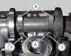
Using a feeler gauge, check the clearance between the opening rocker arm (a) and the lowest point of the camshaft lobe (b), taking care not to compress the rocker arm return spring.
The value must be within the specified ones (sect. 3 - 1.1, Timing system/valves).
If not, remove the opening adjuster (3), as described in paragraph "removing the valves" (sect. 9 - 4.5), And replace it with one of suitable height to obtain the prescribed clearance.
Note
Opening rocker arm shims measuring 1.80 To 3.45 Are available as replacement parts: the size is punched on the shim.
Checking the closing clearance
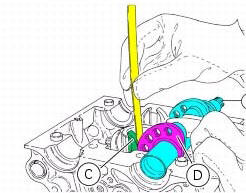
Using a feeler gauge, check the clearance between the closing rocker arm (c) and the highest point of the camshaft lobe (d).
The value must be within the specified ones (sect. 3 - 1.1, Timing system/valves).
If not, remove the closing adjuster (1), as described in paragraph "removing the valves" (sect. 9 - 4.5), And replace it with one of suitable height to obtain the prescribed clearance.
Note
Closing rocker arm shims measuring from 2.2 To 4.5 Are available as replacement parts: the size is punched on the shim.
 Checks and adjustments
Closing shim
Intake side camshaft
Opening shim
Exhaust side camshaft
Valve
Spare parts catalogue
Diavel abs cylinder head: timing system
Diavel abs vertical cylinder head
Diavel a ...
 Checking valve lift
Set the engine to the configuration described for the "checking and adjusting
the valve clearances", previously indicated.
Position the tool 88765.1518 On the cylinder head: the part marked "a" s ...
Other materials:
Radiator fan relay
Introduction
The radiator fans are powered via a specific relay, which is enabled by the
engine control unit.
Component assembling position
A injection relay; b etv relay (throttle valve actuator motor), c radiator
fan relay, d engine control unit.
Location of right hand fan connecti ...
Dtc (ducati traction control) setting function
This function allows you to customise the level of dtc intervention (ducati
traction control) or disable it for every riding
mode.
To access the function it is necessary to view the ""setting" menu", using
buttons (1) "s" or (2) "t" select the "riding
mode" function and press the reset butt ...
Operating principle of dtc
The bbs receives the front and rear speed information from the abs over the
can. Then, the bbs sends the vehicle speed
information to be displayed on the dashboard over the can.
If the tangential speed of the rear wheel exceeds the tangential speed of the
front wheel by a given percentage, t ...