
Ducati Diavel Owners Manual: Clutch lever
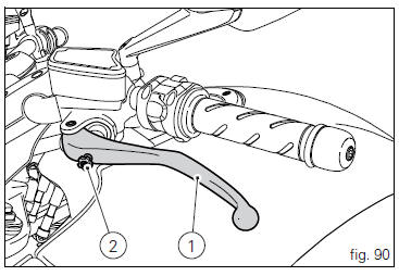
Lever (1) disengages the clutch. It features a dial adjuster (2) for lever distance from the twistgrip on handlebar.
The lever distance can be adjusted through 10 clicks of the dial (2). Turn clockwise to increase lever distance from the twistgrip. Turn the adjuster counter clockwise to decrease lever distance.
When the clutch lever (1) is operated, drive from the engine to the gearbox and the drive wheel is disengaged. Correct use of the clutch lever is very important in all riding situations, especially when moving off.
 Warning
Any adjustment of clutch lever must be carried out when motorcycle is stationary.
 Important
Using the clutch properly will avoid damage to transmission parts and spare the engine.
 Note
Note
It is possible to start the engine with the side stand down and the gearbox in neutral. When starting the bike with a gear engaged, pull the clutch lever (in this case the side stand must be up).
 Lh switch
Dip switch, light dip switch, two positions (fig. 89):
(A) every time pressed down light switches from low
beam on to low beam and high beam
on .
(B) pushed to the side = high
beam ...
 Rh switch
Red on/off switch.
Black engine start button.
The switch (1) has three positions:
Centre: run off. In this position, the engine cannot be
started and all electronic devices are off.
Pu ...
Other materials:
On/off switch on handlebar
Introduction
The on/off switch on the handlebar is used to switch the dashboard on and
off, if a key has been detected, and start the
engine.
With the switch turned to "run off" (centre position), pushing downwards
switches the dashboard on or off (activating
the button inside the switch). ...
Overhaul of the flywheel-alternator assembly
Examine the inner part of alternator rotor (24) for signs of damage. Check
that the starter clutch is working properly and
that the needle races do not show signs of wear or damage of any kind. If there
is any malfunction, remove the whole
assembly.
Disassembling the generator flywheel
U ...
Tank filler plug
Note
To open or close the tank filler plug using the active
key, set the metal part in the middle position, as shown on
page 86.
Opening
Lift the cover (1, fig. 100) And insert the active or passive key
into the lock. Give the key a 1/4 turn clockwise to unlock.
Lift the plug (2, fig. 101) ...