
Ducati Diavel Service Manual: Cylinder compression test
Note
The on-screen icons used during this procedure are explained in a table at the end of this section.
Engine performance is directly correlated to the pressure that can be measured in the combustion chambers of the two cylinders. Pressure which is too high/low or an excessive difference between the two cylinders will cause a drop in engine performance and can cause engine breakdowns.
To reach the vertical head spark plug lift the tank up as specified under the section 8 - 2 "removal of the fuel tank" and fit a drift under it.
Run the engine so that it warms up to the point that the fan is tripped at least once.
Open the throttles completely.
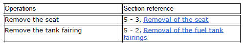
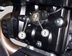
Remove the ht leads (1), unscrewing the nuts (2) of both spark plugs.
Remove the spark plug from the cylinder to be tested.

Connect the ht lead to earth to prevent sparking.
Screw the cylinder compression cable part no.552.1.038.1A into the spark plug compartment.
Connect the pressure sensor part no. 552.1.039.1A to the cable with part no. 552.1.038.1A..
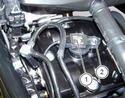
Turn on the dds diagnosis instrument (3) referring to the paragraph "connection to the motorcycle".
Connect the power and diagnosis cable (measurement module) (4) part no. 97900.0222 To the measurement module connector (b) of the dds (3).
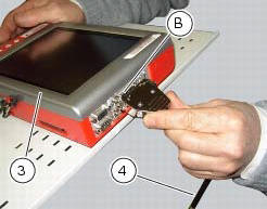
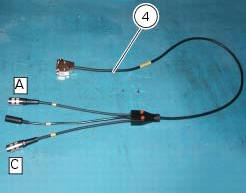
Connect the pressure sensor part no. 552.1.039.1A to the outlet (a) or (c) of cable (4) part no. 97900.0222.
Note
Measure the compression on one cylinder at a time.
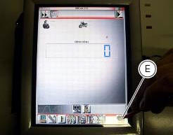
On the dds diagnosis instrument (3), select the "measurement module" function by pressing the corresponding icon; then press the "cylinder compression" icon (d) followed by the "start" icon (e).
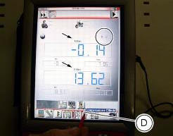
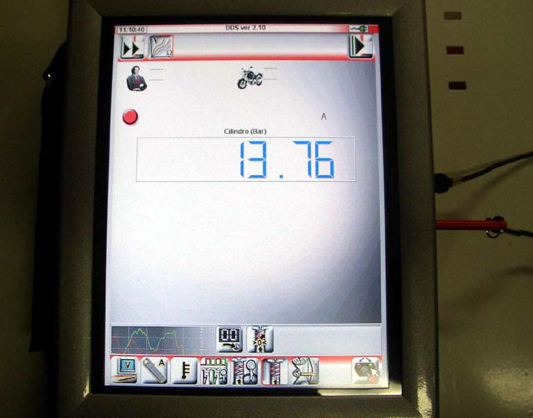
The socket to which the cable (measurement module) (4) is to be connected is indicated on the screen with a capital letter: a, b or c.
Turn over the engine with the starter motor until the pressure stops rising.
Check the pressure in each cylinder:
- Standard value: 11 to 12 bar;
- Minimum value: 10 bar;
- Maximum permissible difference between cylinders: 2 bar.
An excessively high pressure value can be caused by:
- Build up of deposits in the combustion chamber.
An excessively low pressure value can be caused by:
- Gas escaping between the cylinder head and the barrel;
- Worn valve seats;
- Bent valve stems;
- Incorrect valve clearances;
- Worn cylinder or piston rings.
Refit the spark plugs and position the coil-spark plugs wires (1) in the corresponding compartments and tighten the nuts (2) to a torque of 10 nm (min. 9 Nm max. 11 Nm) (sect. 3 - 3, Frame torque settings).

Refit the tank as indicated in section 8 - 2 "refitting the fuel tank".
 Check the engine oil pressure
Note
The on-screen icons used during this procedure are explained in a table at
the end of this section.
To measure the pressure of the lubrication circuit, use the engine oil pressure
test po ...
 Fuel pressure test
Note
The on-screen icons used during this procedure are explained in a table at
the end of this section.
Undo the screws (2) and remove the flange cover (1).
Remove one of the two pipes o ...
Other materials:
Trip 2 meter
This function shows the distance travelled since the trip
meter was last reset (in km or miles depending on the
specific application).
Holding the button (1, fig. 14) ?
pressed for 3 seconds
when this function is displayed resets the trip meter.
When the reading exceeds 9999.9, Distance t ...
Indicating devices
Checking the indicating devices
In the event of a fault, the internal connections of the device must be
checked in all operating conditions. To do this, it is
necessary to disconnect the switch connector from the main wiring harness (sect.
6 - 1, Routing of wiring on frame).
Then analyse th ...
Low battery level
The activation of this (amber yellow) "warning" indicates that the status of
the battery vehicle is low.
It is activated when the battery voltage is ¼ 11.0 Volt.
Note
In this case, ducati recommends charging the battery as soon as possible
with the specific device, as it is possible th ...