
Ducati Diavel Service Manual: Fuel pressure test
Note
The on-screen icons used during this procedure are explained in a table at the end of this section.
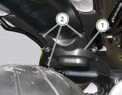
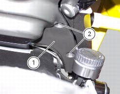
Undo the screws (2) and remove the flange cover (1).

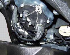
Remove one of the two pipes of the fuel system (3).
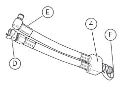
Use the fuel pressure pipe (4) part no. 590.1.189.1A by connecting one end (d) to the coupling of the delivery pipe to the tank and the other end (e) to the fuel system pipe (3): in this way you create a pressure pick-up socket (f).
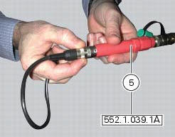
Connect the pressure sensor (5) part no. 552.1.039.1A to the outlet (f) of hose (4), in order to convert the pressure reading into an electric signal.
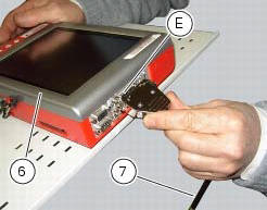
Turn on the dds diagnosis instrument (6) referring to the paragraph "tester power supply".
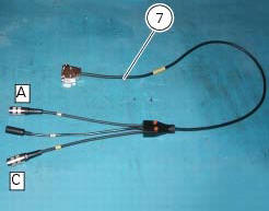
Connect the power and diagnosis cable (measurement module) (7) part no. 97900.0222 To the measurement module connector (e) of the dds (1).
Connect the pressure sensor (6) part no. 552.1.039.1A to outlet (a) or (c) of the cable (7).
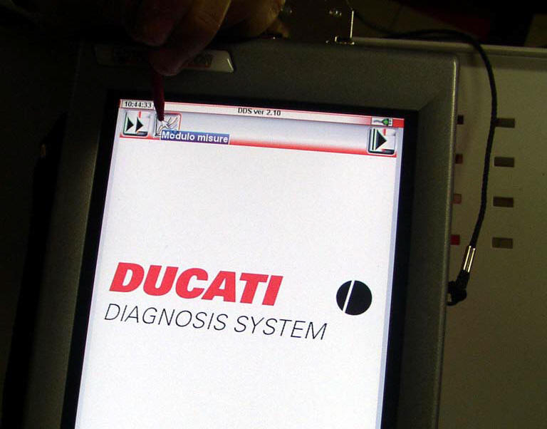
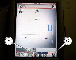
On the dds diagnosis instrument (6), select the "measurement module" function by pressing the corresponding icon; then press the "pressure test" icon (f) followed by the "start" icon (g).
The socket to which the cable (measurement module) (7) is to be connected is indicated on the screen with a capital letter: a, b or c.
The values may be displayed in three different ways: in one numeric form and in two graphic forms; to select the desired display type, press the "value display" icon (h).
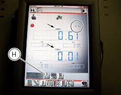
The measured value is indicated alongside the letter (a) or (c) identifying the cable used for the measurement: i.E. If you used socket (a) of the cable (7), the value measured will be displayed next to the letter (a) on the screen.
The maximum pressure must be equal 3 bar (nominal).
Once the test is over, remove all the components of the test instrument and refit the fuel system pipe (3).

Refit the flange cover (1) by tightening the screws (2) to a torque of 4 nm +/- 10% (sect. 3 - 3, Frame torque settings).

 Cylinder compression test
Note
The on-screen icons used during this procedure are explained in a table at
the end of this section.
Engine performance is directly correlated to the pressure that can be
measured in the com ...
 Guided diagnosis
Note
The on-screen icons used during this procedure are explained in a table at
the end of this section.
The dds diagnosis instrument guides the operator step-by-step through the
various diagnos ...
Other materials:
Trip 1 meter
This function shows the distance travelled since the trip meter was last
reset (in km or miles depending on the specific
application).
Press and hold (1) "s" for 3 seconds while in this function to reset the trip
odometer.
When the reading exceeds 9999.9, Distance travelled is reset and t ...
Key-on/key-off using the red key on the handlebar with the active key
A key-on can be performed by pressing the red key (6) on
the handlebar in the hands free on/off position and in
the presence of the active key (3, fig. 77).
Note
The active key (3, fig. 77) Has a range of approx. 1.5 M,
therefore it must be located within this range.
Key-off can be performed ...
Explanation of the function of the ride-by-wire system
Mechanism
Via metal cables, the throttle grip operates a roller mounted on one end of a
spindle located near the horizontal cylinder
throttle valve spindle.
The aps sensor, which measures the position of the throttle grip itself, is
mounted on the opposite end of this spindle.
A mechanic ...