
Ducati Diavel Service Manual: Testing the battery charging system
Note
The on-screen icons used during this procedure are explained in a table at the end of this section.
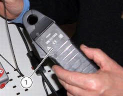
You can determine the engine rpm required for generator to produce just enough current to charge battery, feed the injection ignition system and all electric items fitted to motorcycle. When applied to a cable, the clamp-type amperemeter (1) part no. 88765.1126V detects the magnetic field generated by the current passing through that cable.
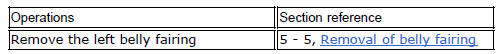
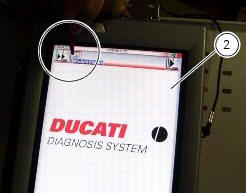
Turn on the dds diagnosis instrument (2) referring to the paragraph "tester power supply".
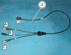
Connect the power and diagnosis cable (measurement module) (3) part no. 97900.0222 To the measurement module connector (d) of the dds (2).
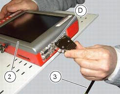
Connect the clamp-type amperemeter (1) to the connector (e) of the power and diagnosis cable (measurement module) (3).
Warning
The clamp-type amperemeter must not be connected to wires through which electrical current is flowing.
Insert the clamp-type amperemeter into the battery positive terminal lead with the arrow on the clamp pointing towards the battery positive terminal (+).
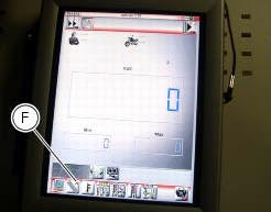
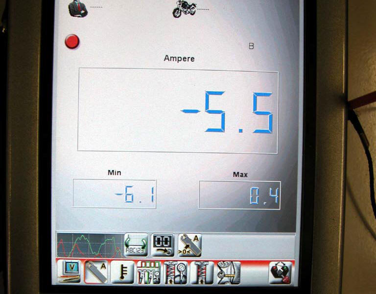
On the dds diagnosis instrument (2), select the "measurement module" function by pressing the corresponding icon; then press the "ammeter" icon (f) followed by the "start" icon.
The socket to which the cable (measurement module) (3) is to be connected is indicated on the screen with a capital letter: a, b or c.
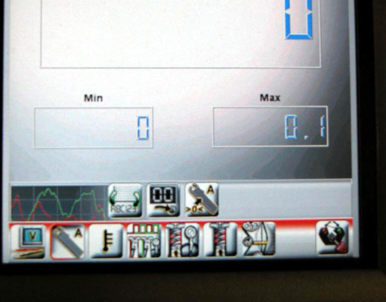
If the measured current is a positive quantity, it means that generator is feeding all electric items and charging battery at the same time. If the current has a negative sign, this means that the charging system is not able to power the electrical loads and a significant amount of the current required must be supplied by the battery, which is therefore discharging.
Important
If polarity is reversed when clamping the ammeter onto the cable, the sign of the readings will also be reversed, giving rise to incorrect diagnosis.
 Guided diagnosis
Note
The on-screen icons used during this procedure are explained in a table at
the end of this section.
The dds diagnosis instrument guides the operator step-by-step through the
various diagnos ...
 Deactivating the service indication on the dashboard
The message "serv" is displayed on the dashboard, indicating that the
motorcycle should be serviced in accordance with
the programmed maintenance plan. This indication is activated after the first ...
Other materials:
Side stand button
Introduction
The side stand button is located on the side stand. Together with the signal
from the clutch button and the neutral signal
generated by the gear sensor (transmitted to the engine control unit over the
can line), the side stand position signal is
used to enable or disable engine s ...
Removal of the shock absorber support
Remove the rear brake master cylinder (sect. 7 - 4, Removing of the rear
brake control).
Remove the rear shock absorber (see removal of the rear shock absorber of this
section).
Loosen the screws (2) and (7) and their nuts (35).
Remove the side stand (sect. 7 - 16, Removing of the ...
How to turn the motorcycle off
To turn the motorcycle off, turn the switch from "run on" to "run off". The
engine stops. To switch the dashboard off,
push the on/off switch downwards. When released, the switch automatically
returns to the "run off" position.
Push the switch downwards to switch the engine off and enter " ...