
Ducati Diavel Service Manual: Overhaul of cylinder head components
Cylinder heads
Remove any carbon deposits from the combustion chamber and its ducts.
Remove any scale from the coolant ducts.
Check for cracking and inspect the sealing surfaces for scoring, ridges or other damage.
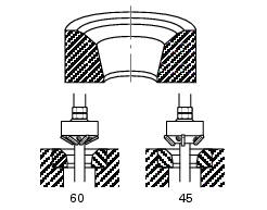
Check that the cylinder barrel mating surfaces of the cylinder head are free of carbon deposits and scale. If this is not the case, spread diamond dressing compound (6 to 12 micron thickness) on a reference surface and slide the cylinder head on the surface as shown in the figure until a flat finish is obtained.
Valve seats
Visually inspect the valve seats: for cracking or pitting.

Minor damage can be repaired by grinding with special 45 and 60 single-blade grinders. Grind the valves and check the seal.
If the valve seats are excessively damaged, fit oversize seats. Replacement seats are available with 0.03 And 0.06 Mm oversized outside diameters.
Important
When you change the valve seats, change the valve guides as well.
Proceed as follows.
Remove the worn seats, grinding carefully to avoid any damage to cylinder head bores.
Check the diameter of head bores and choose the oversized valve seat that will give an interference fit of 0.04 To 0.10 Mm.
Heat the cylinder head gradually and evenly up to 150 C and chill the new valve seats in dry ice.
Drive the seats perfectly square into the head bores using the appropriate valve guide seat installer 88713.2846 And 88713.2847.
Allow the cylinder head to cool down and grind the seats to the following dimensions: ca = ø 41.6 +/- 0.025 Mm.
Cs = ø 33.6+/-0.025 Mm.
S = 1.2 Mm.
D = 0.2 To 0.4 Mm.
Important
Do not use any lapping compound after final grinding.
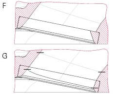
It is advisable to smooth the joint between the intake valves seats and the intake ducts (f = before; g = after).
Valve guides
Check internal surface of the valve guides: for cracking or distortion.
Thoroughly check the dimensions of the inner surface of the valve guide. Measure the inside diameter with a bore diameter gauge.
Measure the diameter at different positions of the valve guide.
The assembly clearance must be: highest measured value - lowest measured value = 0.03 To 0.045 Mm; the maximum permissible wear limit is 0.08 Mm.
Change the valve guides when the ovality exceeds permissible limit or the clearance to the valve stem is outside the tolerance range.
When you change the valve guide, you must also change the valve.
Valve guides as spare parts are available with outside diameter oversized by 0.03, 0.06 And 0.09 Mm.
Change the valve guides as follows:
- Heat up the cylinder head gradually and evenly up to 150 C;
- Remove the original valve guides using tool no. 88713.2842;
- Allow the cylinder head to cool down and check the condition of the seats;
- Choose suitable valve guides to obtain an interference fit in the cylinder head of 0.022 To 0.051 Mm;
- Heat up the cylinder head again and chill the new valve guides in dry ice;
- Lubricate the bores in the cylinder head and install the valve guides using the appropriate service tools and in reference to the dimensions given in the figure;
A= 22.4+/-0.15 Mm.
B= 28.45+/-0.15 Mm.
Hone the mating surface with a reamer.
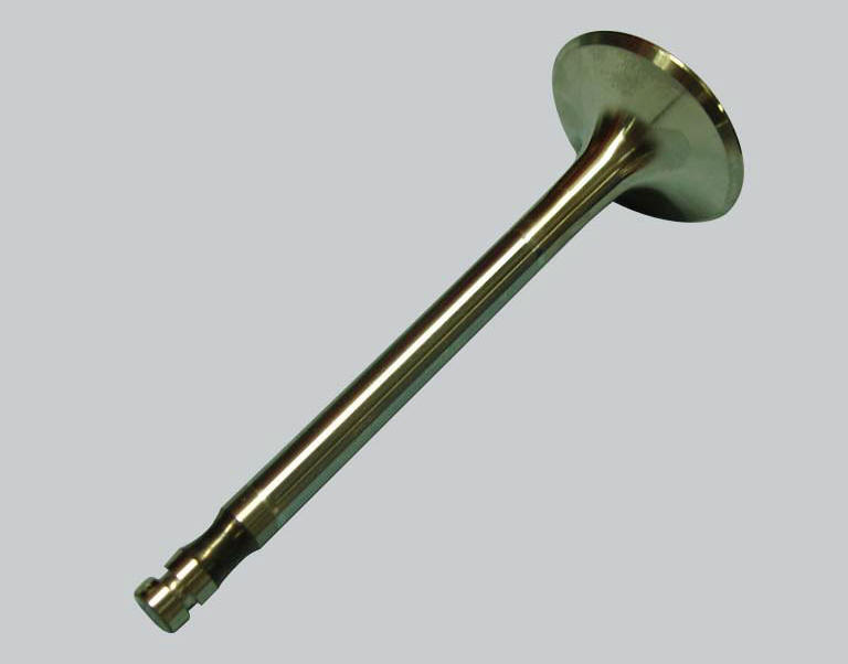
Checking the valve
Check that the stem and the valve seat contact surface are in good condition.
There must be no pitting, cracks, deformations or signs of wear.
Warning
The valves cannot be ground.
Perform the following checks.
Measure the diameter of the valve stem at various points along the section that runs in the valve guide.
Check the valve stem for buckling. Place it on a "v" block and measure deformation with a dial gauge.
Service limit: 0.053 Mm.
Check the valve stem for buckling. Place valve on a "v" block, set a dial gauge perpendicular to head and measure runout of valve face at 45.
- Nominal concentricity: 0.01 Mm;
- Service limit: 0.03 Mm.
Use prussian blue or a mixture of minimum and oil to check that the contact surface (w) between the valve and seat is 1.4 To 1.6 Mm (1.05 To 1.35 Mm when new). Grind the seat if the dimension measured is greater than the above limit.
Checking the valve seal
After grinding the seats it is important to check the seal between the valve face and the seat: if the seat contact area (s) on the valve is wider than the 45 band (w) this could lead to poor sealing.
Checking the rocker arms
Check for signs of wear, grooves or chrome flaking off.
Check the condition of rocker arm bore and shaft.
Assembly clearance: 0.025 To 0.049 Mm.
Wear limit: 0.08 Mm.
Opening and closing shims - springs
Check the condition of the contact surfaces of the valve opening and closing shims: there must be no signs of wear.
Check the condition of the closing rocker arm return springs: check for cracking, distortion, or loss of elasticity.
 Removing the valve rocker arms
With the cylinder head in the condition described in the previous paragraph,
remove the rocker arms.
Unscrew the eight plugs (12) and recover the seals (15).
Using an m6 screw, withdraw ...
 Reassembly of the cylinder head
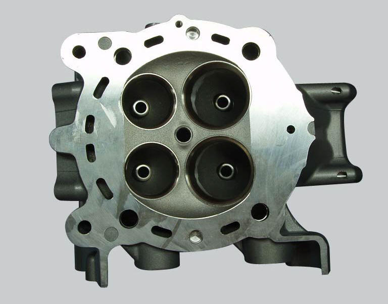
The exhaust side can be identified by the three threaded holes on the flange.
The intake side can be identified by the presence of four threaded holes on
the flange.
All the photos in this ...
Other materials:
Refitting the filler cap
Position seal (18) in tank cap (10) as shown and reassemble following the
removal procedure in the reverse sequence.
In particular tighten the screws (17) to a torque of 3 nm +/- 10% (sect. 3 - 3,
Frame torque settings).
...
Removal of the rear brake calliper
Important
The brake manufacturer advises against any servicing of the internal
components of brake callipers or the master cylinder.
Incorrect overhaul of these critical safety components can endanger rider and
passenger safety.
Before removing the parts in question, you must first carry ou ...
Removal-refitting of the engine assembly
Screw
Special screw
Nut
Screw
Swingarm pivot
Special screw
Washer
Spare parts catalogue
Diavel abs frame
Diavel abs swingarm
Diavel carbon
abs
frame
Diavel carbon
abs
swingarm
Important
Bold reference numbers in this section identify parts not shown in the
figures a ...