
Ducati Diavel Service Manual: Removing the valve rocker arms
With the cylinder head in the condition described in the previous paragraph, remove the rocker arms.
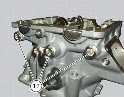
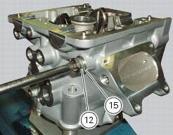
Unscrew the eight plugs (12) and recover the seals (15).
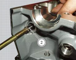
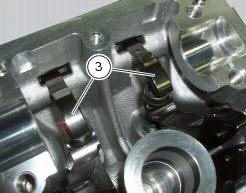
Using an m6 screw, withdraw the shafts (2) of the opening rocker arms (3) on the exhaust and intake sides.
Remove the opening rocker arms (3).
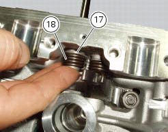
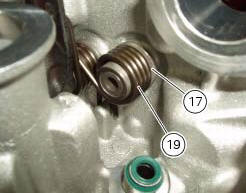
Using the claw of the rocker arm spring tensioning kit 88713.2069 Installed between the spring and the inner wall of the cylinder head, move the straight end of the rocker arm return spring (19) and (18) and insert it in the drilled shaft.
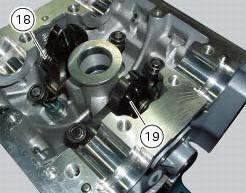
Use the shaft to slide the end of the spring into its final position.
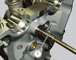
Using an m6 screw, withdraw the shafts (1) of the closing rocker arms on the exhaust and intake sides.
Remove the closing rocker arms (4) and (16), the springs (18) and (19) with the spacers (17).
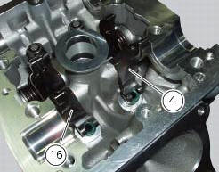
Carry out the same operation to remove the closing rocker arms (4) and (16), the springs (24) and (25) with the spacers (23).
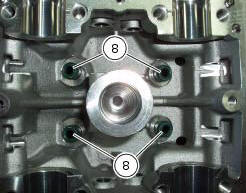
Remove the sealing rings (8) from the ends of the valve guides.
Repeat the same procedure for the other cylinder head.
 Removing the valves
Raise the rocker arm (3) and remove the opening shim (5) from the valves with
a pair of pliers.
Push down the closing rocker arms (16) and (4) and the closing shim (7).
Remove the half r ...
 Overhaul of cylinder head components
Cylinder heads
Remove any carbon deposits from the combustion chamber and its ducts.
Remove any scale from the coolant ducts.
Check for cracking and inspect the sealing surfaces for scoring, ri ...
Other materials:
Tank filler plug
Note
To open or close the tank filler plug using the active
key, set the metal part in the middle position, as shown on
page 86.
Opening
Lift the cover (1, fig. 100) And insert the active or passive key
into the lock. Give the key a 1/4 turn clockwise to unlock.
Lift the plug (2, fig. 101) ...
Removal of the timing belt covers
Loosen the screws (4) securing the central external cover (1) and remove it
from the central side.
Undo the fixing screws (4) of the external cover (25) and remove it from the
vertical thermal unit.
Undo the fixing screws (4) of the external cover (3) and remove it from the
horizonta ...
Draining the clutch hydraulic circuit
Warning
Clutch fluid will damage painted surfaces if spilled on them. It is
also very harmful if it comes into contact with the skin or
with the eyes; in the case of accidental contact, wash the affected area
thoroughly with plenty of running water.
Remove the dust cap to expose the bleed val ...