
Ducati Diavel Service Manual: Removal of the oil pump
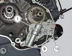
Undo and remove the screws (9) and (10) securing the pump assembly.
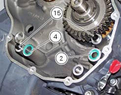
Remove the oil pump assembly (1) and extract the o-rings (2) and (4) from the crankcase half together with two locating bushes (15).
 Oil pump
Complete oil pump assembly
O-ring
Circlip
O-ring
Pump body
Circlip
Reducer bush
Spring washer
Screw
Screw
Spring washer
Pump drive gear
Key
By-pass plug
Locating bus ...
 Disassembly of the oil pump
Hold the oil pump (1) in a vice taking care not to damage the drive gear
(12).
Warning
Make sure that vice jaws are faced with soft material.
Remove the plug (14) and extract the spring (16) ...
Other materials:
Location of elements on motorcycle
(A) injection relay; (b) etv relay (throttle valve operating engine); (c)
radiator fan relay; (d) hands free relay.
(E) ecu; (g) bbs (black box system or central electronics); (f) abs hydraulic
unit with integrated control unit.
Fuses located at the rear left of the vehicle.
...
Carrying the maximum load allowed
Your motorcycle is designed for travelling over long
distances with a full load in complete safety.
Even weight distribution is critical to preserving these safety
features and avoiding trouble when performing sudden
manoeuvres or riding on bumpy roads.
Warning
Do not exceed the total permi ...
Low hands free key (hf) battery level
The activation of this (amber yellow) "warning" indicates
that the hands free system has detected that the battery
that permits the active key (1, fig. 62) To communicate and
turn the vehicle on is almost discharged.
Note
In this case, ducati recommends replacing the battery
as soon ...