
Ducati Diavel Service Manual: Overhaul of the flywheel-alternator assembly
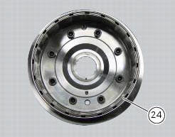
Examine the inner part of alternator rotor (24) for signs of damage. Check that the starter clutch is working properly and that the needle races do not show signs of wear or damage of any kind. If there is any malfunction, remove the whole assembly.
Disassembling the generator flywheel
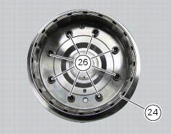
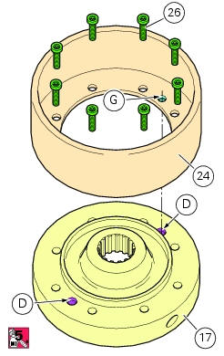
Unscrew the 8 screws (26) and remove the rotor (24) from the flywheel.
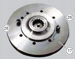
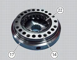
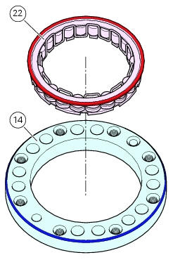
Insert two of the screws (26) just removed from the flywheel rotor-side in their holes in order to remove the flange (14) and the starter clutch (22) from the flywheel (17). The starter clutch is a slight interference fit on the flange. To remove it, use a suitable drift.
Reassembling the flywheel - generator assembly
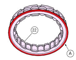
Install the starter clutch (22) in the flange (14) to bring the edge (a) of the clutch up against the flange.
Important
Assemble the components (starter clutch and flange) so that the edge (a) of the starter clutch is positioned on side of the flange with the bevelled edge (b).
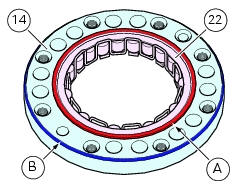
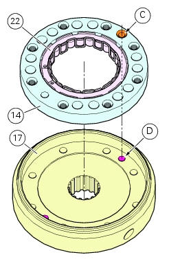
Seat the flange (14) with the starter clutch (22) in the flywheel (17), aligning the flange locating hole (c) with the flywheel locating hole (d).
Note
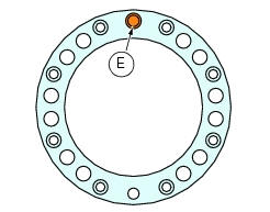
The flange locating hole (c) is the hole with the countersunk lead-in (e).
Note
The locating hole (d) of the flywheel can be either one of the two holes (f).
Note
Use suitable tools to align the locating holes.
Important
Assemble the components (flange and flywheel) so that edge (a) of the starter clutch (22) is enclosed between the flange and flywheel.
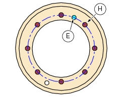
Install the rotor (24) on the flywheel (17), aligning one of the flywheel locating holes (d) with the rotor locating hole (g).
Note
The rotor locating hole (g) is the hole positioned on the same diameter as the fixing holes (h).
Note
Use suitable tools to align the locating holes.
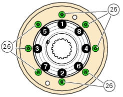
Apply threadlocker to the rotor-flywheel fixing screws (26) and start them in their threads.
Tighten
Tighten the screws (26) to a torque of 13 nm (min. 11 Nm - max. 15 Nm) (sect. 3 - 3, Engine torque settings) following the sequence above.
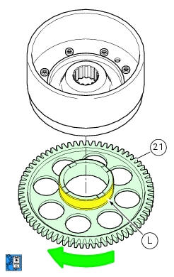
Lubricate the surface (l) of the driven gear (21) with engine oil.
Install the driven gear on the starter clutch, ensuring it is properly seated.
Note
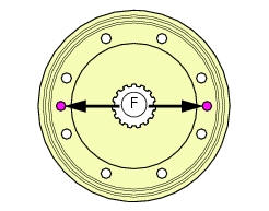
To facilitate installation, rotate the driven gear in the direction of the green arrow.
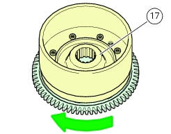
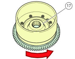
Hold the flywheel (17) with one hand and check that the driven gear can rotate freely in the direction of the green arrow but not in the direction of the red arrow.
If either of these two conditions is not met, this means that the starter clutch has not been installed correctly.
 Removing the flywheel - generator assembly
Use the tool 88713.3367 Fixed to the m10 side stand fixing holes (d).
Secure the tool to the flywheel with the screws (e).
Unscrew the alternator-flywheel retaining nut (15).
Warning
While uns ...
 Refitting the flywheel-alternator assembly
Fit the roller cage unit (20) with washer (18) and internal ring (19),
applying prescribed grease on the washer (18).
Install the roller cage assembly (20) with the washer (18) and inner race
...
Other materials:
Electrical components support
Clip
Screw
Voltage regulator
Battery fixing bracket
Battery support
Vibration damper mount
Hose clip
Vibration damper mount
Clip
Washer
Screw
Cover
Cable grommet
Battery
Battery mat
Screw
Bracket
Solenoid starter
Spring washer
Spacer
Screw
Horn
Scre ...
Riding mode customisation
This function customises each riding style.
To access the function it is necessary to view the ""setting" menu", using
buttons (1) "s" or (2) "t" select the "riding
mode" function and press the reset button (3) to enter the following page.
When accessing the function, the three riding modes ...
Abs system operating information
The response of the system is based on the analysis of the speed signals for
front and rear wheels; the system is
automatically deactivated if either of these signals is missing.
Note
In the event of the abs control unit detecting a fault in the abs
electronic management system, it activates ...