
Ducati Diavel Service Manual: Refitting the flywheel-alternator assembly
Fit the roller cage unit (20) with washer (18) and internal ring (19), applying prescribed grease on the washer (18).
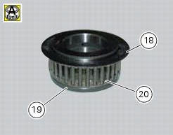
Install the roller cage assembly (20) with the washer (18) and inner race (19).
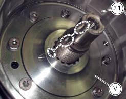
Install the flywheel assembly (v) with the gear (21), aligning the notches as shown in the photo.
Fit the washer (16) on the end of the crankshaft.
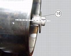
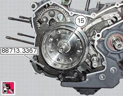
Apply the recommended threadlocker to the thread on the end of the crankshaft and the nut (15).
Start the nut (15) on the crankshaft.
Lock the flywheel rotation by means of tool number 88713.3367 And tighten the nut (15) to a torque of 330 nm (min.
313 Nm - max. 346 Nm) (sect. 3 - 3, Engine torque settings).
 Overhaul of the flywheel-alternator assembly
Examine the inner part of alternator rotor (24) for signs of damage. Check
that the starter clutch is working properly and
that the needle races do not show signs of wear or damage of any kind. If ...
 Refitting the alternator-side crankcase cover
Before the assembly make sure that the water pump unit is fitted on the
generator cover (sect. 9 - 3.3, Refitting the
water pump).
If bearing (27) has been removed, lubricate its seat with speci ...
Other materials:
Removing outer components
Note
The following removal operations are required in order to renew and/or
clean the crankcase halves. If the original
crankcase halves are to be reused, then the removal of these components is not
essential.
Unscrew the screw (17) and remove the oil breather valve (1) with the o-rings
...
Removal of the gear selector lever
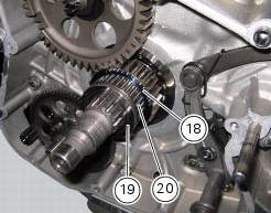
Unscrew and remove the fixing screws (18) and (20) of the complete gear
selector lever (21) and collect the spacer (19).
Remove the gearchange mechanism complete with the shaft, spring, and stop plate.
Important
Visually inspect the gear selector claw (14) for wear, particularly aroun ...
Suspensions
Front
Hydraulic upside-down fork provided with external adjusters
for rebound and compression damping and preload (for inner
springs of fork legs).
Stanchion diameter:
50 mm, coated.
Rear wheel travel:
120 mm
Rear
The shock absorber is adjustable for rebound and
compression, with remot ...