
Ducati Diavel Service Manual: Rectifier-regulator
The rectifier (1) is placed in the electrical components compartment.
The rectifier/regulator consists of an aluminium casing containing the diodes that rectify the current produced by the alternator. It also contains an electronic device that regulates the current supplied by the alternator in accordance with battery voltage.
If the battery is drained, the current has the value necessary to restore optimum operating conditions of the battery. In contrast, if the battery is fully charged, the current value will be lower.
Note
Control the charger current by using the dds diagnosis instrument (sect. 6 - 11, Diagnostic instruments).
Removal of the regulator 
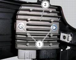
Undo the two fixing screws (1) of the voltage regulator (2) and remove it together with them.
Important
Do not disconnect the battery cables when engine is running because this would cause irreparable damage to the regulator.

Refitting the regulator
Position the regulator (1) on the support.
Tighten the screws (1) to a torque of 10 nm +/- 10% (sect. 3 - 3, Frame torque settings).
Important
Do not disconnect the battery cables when engine is running because this would cause irreparable damage to the regulator.
Regulator fuse
The 30 a fuse is located inside the solenoid starter in the electrical components compartment.
Remove the fuse cap (a) to reach it.
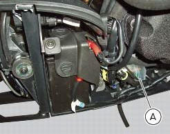
A blown fuse can be identified by breakage of the inner filament (b).
Important
To avoid possible short circuits, replace the fuse in key off condition.
Warning
Never use a fuse with a rating other than the specified value. Failure to observe this rule may damage the electric system or even cause fire.
 Alternator
It is equipped with a 12 v, 430 w generator, consisting of a fixed element
(stator, a) located on the generator cover and
of a movable element (rotor, b) fixed to the crankshaft.
Note
To chec ...
 Electric starting system
Note
The references of the elements listed below are those of the "wiring
diagram", sect. 6 -1.
Electric starting system
The key components of the electric starting system are a solenoid (6) and ...
Other materials:
Removing the timing belt driveshaft pulleys
Use the tool code 88713.1805 To hold the driving pulley on the engine
crankcase against rotation.
Important
If this operation is carried out with the engine installed in the frame,
hold the driveshaft pulleys against rotation using the
tool code 88713.2011 Mounted on the alternator cover.
Lo ...
Recovery in the event of flat active key battery
If the active key battery is running low or is flat, the hands free system
shows the relative icon on the dashboard.
The following image shows the icon appearing on the circular area of the
dashboard: this indicates that the active key
battery is flat.
For the replacement procedure of t ...
Removal of the gearbox assembly
Withdraw the selector fork shafts (30).
Move the forks (28) and (29) to disengage them from the slots in the selector
drum (14).
Withdraw the selector drum (16) taking care not to lose shims (31) and (27)
mounted on the shaft. Note that the
positions of the shims must not be inverte ...