
Ducati Diavel Service Manual: Refitting the clutch-side crankcase cover
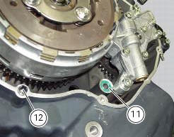
Clean and degrease mating surfaces on the clutch-side crankcase half cover and crankcase and ensure that locating bush (12) and the o-ring (11), located in correspondence with the oil way, are installed in the crankcase.
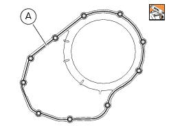
Apply an even, regular bead of ducati liquid gasket (a) on the mating surface of the crankcase half and around all holes.
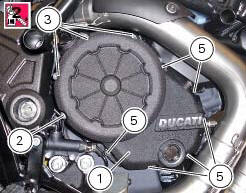
Fit the cover assembly (1) to the crankcase half and insert the retaining screws.
Apply recommended threadlocker to the screws (2), (3) and (5).
Lock the screws (2), (3) and (5) to a torque of 10 nm (min. 9 Nm - max. 11 Nm) (sect. 3 - 3, Engine torque settings) in a cross-pattern sequence.
 Reassembly of the clutch-side crankcase cover
Fit the plug (14) and the gasket (13). Fit the plug (17) and the gasket (15).
If the bush has been replaced, fully seat the new bush (7) in the slot in the
cover using a suitable drift and a pr ...
 Primary drive gears
Clutch drum/primary drive gears
Spacer
Threaded ring nut
Lock washer
Spare parts catalogue
Diavel abs clutch
Diavel abs connecting rods
Diavel carbon
abs
clutch
Diavel carbon
ab ...
Other materials:
Hands free key (hf) not recognised
The activation of this (amber yellow) "warning" indicates
that the hands free system does not detect the active key
(1, fig. 62) Near the vehicle.
Note
In this case, ducati recommends checking that the
active key (1, fig. 62) Is near the vehicle (and has not been
lost) and that it f ...
Carrying the maximum load allowed
Your motorcycle is designed for travelling over long
distances with a full load in complete safety.
Even weight distribution is critical to preserving these safety
features and avoiding trouble when performing sudden
manoeuvres or riding on bumpy roads.
Warning
Do not exceed the total permi ...
Key-on/key-off using the red key on the handlebar with the passive key
A key-on can be performed by pressing the red button (6) on
the handlebar in the hands free on/off position and in
the presence of the passive key (4, fig. 77).
Note
The passive key (4, fig. 77) Has a range of a few cm,
therefore the key (4, fig. 77) Must be positioned near the
antenna (2). R ...