
Ducati Diavel Service Manual: Refitting the engine
Refitting is the reverse of removal.
Important
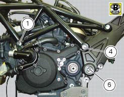
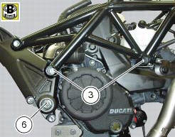
Apply recommended grease and tighten the special screws (6) to a torque of 60 nm +/- 5% (sect. 3 - 3, Frame torque settings).
Tighten the nuts (3) to a torque of 48 nm +/- 5% (sect. 3 - 3, Frame torque settings).
Warning
For the assembly sequence of nuts and screws refer to sect. 7 - 17, Reassembling the frame and the lateral footrests.
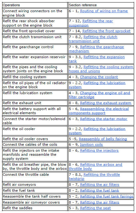
Refit the removed parts by performing the steps shown in the table and in the specific sections of the manual in reverse order.
 Removal of the engine
In order to remove engine you must first remove a series of other components
from the motorcycle.
Most of these removal procedures are described in the relative sections of this
manual.
The ...

Other materials:
Lap activation/deactivation function (lap time)
This function activates and deactivates the lap function (lap
time).
To access the function it is necessary to view the "setting" menu page 48, using
button (1, fig. 14) ?"
" or (2, fig. 14) ?" " select the "lap" function and
press the reset button
...
Cylinder/piston assemblies
Piston
Gudgeon pin circlip
Gudgeon pin
Set of piston rings
Cylinder-crankcase gasket
Water pump outlet union
Hose clip
Horizontal cylinder coolant inlet hose
Vertical cylinder coolant inlet hose
Cylinder barrel
Cylinder head gasket
Bush
Spare parts catalogue
Diavel a ...
Traction control (dtc) deactivated
The activation of this (amber yellow) "warning" indicates
that dtc (ducati traction control) has been turned off.
Note
In this case, ducati recommends being very careful
when riding as the vehicle behaviour will be different in
comparison to when operating with the traction control
...