
Ducati Diavel Service Manual: Refitting the fuel tank
If the fuel tank has been disassembled into its component parts, reposition all the parts as shown in the exploded view.
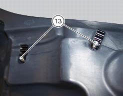
In particular: tighten the screws (13) to a torque of 5 nm +/-10% (sect. 3 - 3, Frame torque settings).
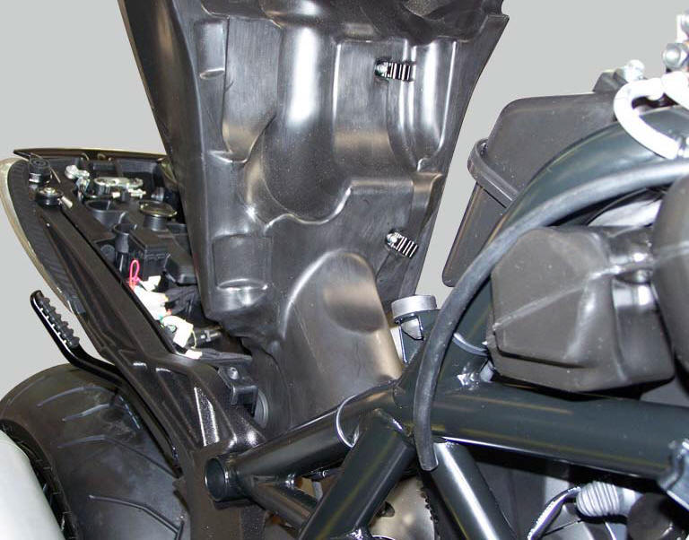
Refit the tank by inserting its rear side into the pin on the frame, as shown in the figure.
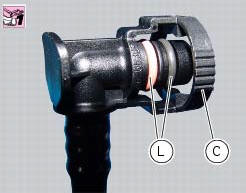
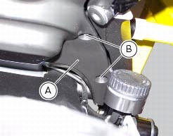
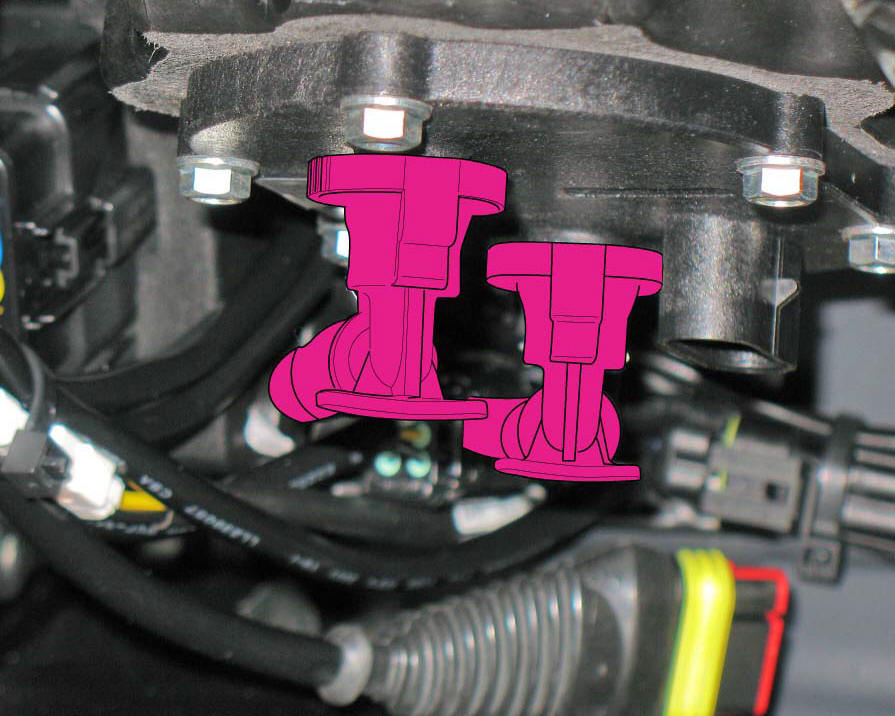
Smear the o-rings (l) installed on fuel hose couplings (c) with rubber lubricant.
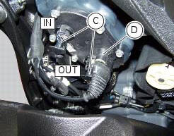
Connect the two quick-release fittings (c) of the fuel pipes following the removal order, paying attention to insert the Delivery on the filler marked with out and the return on the filler marked with in.
Connect connector (d) of the fuel level sensor to the main wiring.
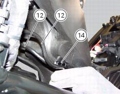
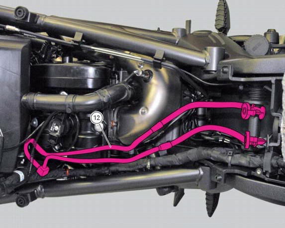
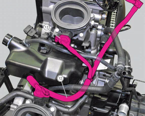
Attach the fuel hoses (12) to the hose clips (14).
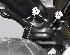
Refit the flange cover (a) by tightening the screws (b) to a torque of 4 nm +/- 10% (sect. 3 - 3, Frame torque settings).
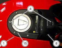
Position, without tightening, the front retaining screw (4).
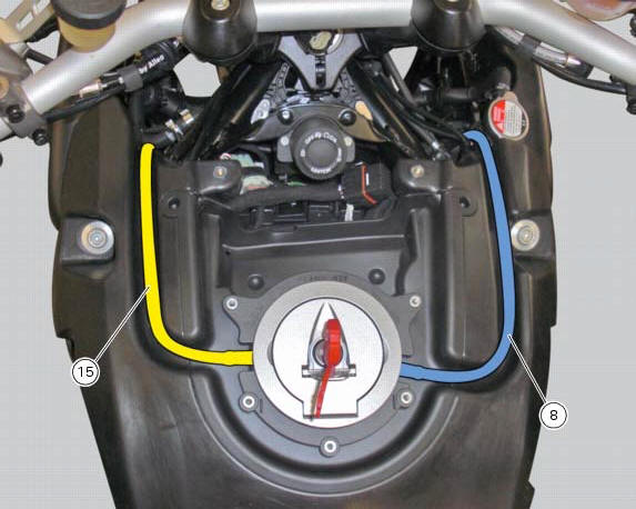
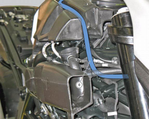
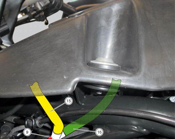
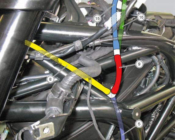
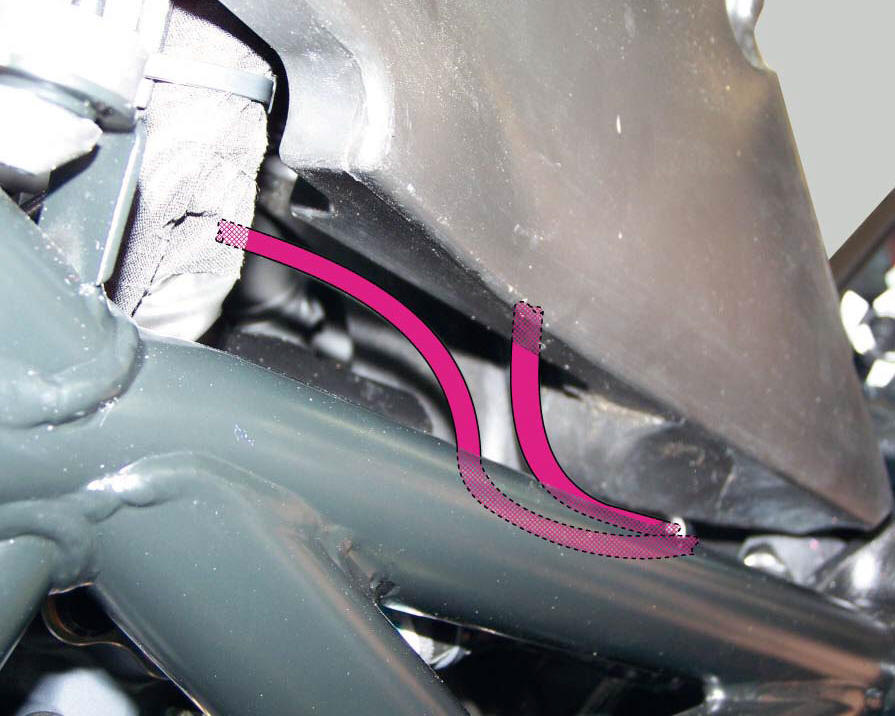
On both sides of the tank plug, place the two breather pipes (8) and (15) and insert them on the plug.
Check correct position of the tank (1) and tighten the two front retaining screws (4) to a torque of 10 nm +/- 10% (sect. 3 - 3, Frame torque settings).
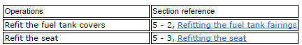
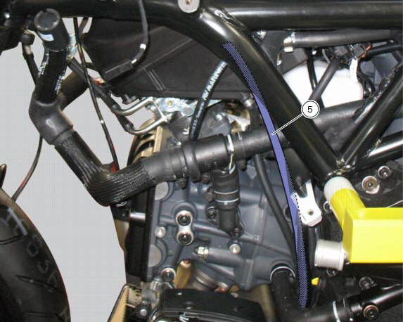
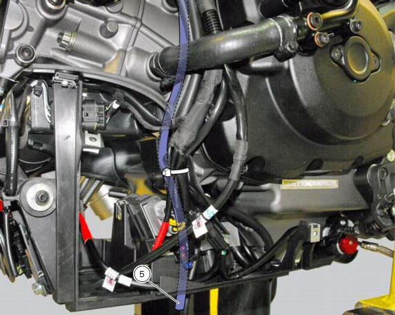
Positioning of the fuel tank breather and drain hoses
 Refitting the fuel tank flange
Insert the flange (20) in its housing in the fuel tank.
Apply prescribed threadlocker to the screws (9) and tighten to a torque of 6 nm
+/- 10% (sect. 3 - 3, Frame torque
settings), following th ...
 Airbox - throttle body
Airbox
O-ring
Injector
Throttle body assembly
Screw
Clamp
Intake manifold
Screw
Pressure sensor
Screw
Clamp
Hose
Sealing washer
Intake manifold
Sealing washer
Scre ...
Other materials:
Low beam lights not working
Location of connections and components
(A) injection relay; (b) etv relay (throttle valve operating engine); (c)
radiator fan relay; (d) hands free relay.
Fuses located at the rear left of the vehicle.
(1) 10A dashboard; (2) 5a engine control unit; (3) 15a key-sense; (4) 20a
injecti ...
Dtc (ducati traction control) setting function
This function allows you to customise the level of dtc
intervention (ducati traction control) or disable it for every
riding mode.
To access the function it is necessary to view the "setting" menu page 48, using
button (1, fig. 14) ?"" or (2, fig.
14) ?" " sele ...
Stored lap display function
This function displays the stored laps.
To access the function it is necessary to view the ""setting" menu", using
buttons (1) "s" or (2) "t" select the "lap"
function and press the reset button (3) to enter the following page.
Use button (1) "s" or (2) "t" to select "lap data" indication a ...