
Ducati Diavel Service Manual: Refitting the intake manifold and coolant union
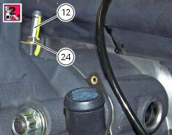
Apply prescribed threadlocker to the fitting (12), start it with seal (24) and tighten it to a torque of 2.5 Nm (min. 2 Nm - max. 3 Nm) (sect. 3 - 3, Frame torque settings).
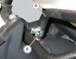
Install the pipe (b) and tighten the clamp (a) to the torque of 1 nm +/- 10% (sect. 3 - 3, Engine torque settings).
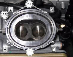
Check that the mating surfaces of the cylinder head and manifold are perfectly flat and clean and install the intake manifold (25) on the cylinder head.
Lock the fixing screws (21) to the torque of 10 nm (min. 9 Nm - max. 11 Nm) (sect. 3 - 3, Engine torque settings) in a cross-pattern sequence (1-2-3-4).
 Removal of the intake manifold and coolant union
Loosen the clips (f) and remove the hoses (t).
Remove the manifolds (25) undoing the screws (21).
Loosen the clamp (a) and remove the hose (b). Remove the union (12) and
recove ...
 Valves - rocker arms
Closing rocker arm shaft
Opening rocker arm shaft
Opening rocker arm
Closing rocker arm (left)
Valve opening shim
Half rings
Valve closing shim
Sealing ring
Valve guide
Exhaus ...
Other materials:
Total distance covered indicator: "odometer"
This function shows the total distance covered by the vehicle
(in km or miles depending on the specific application).
At key-on the system automatically enters this function.
The odometer reading is stored permanently and cannot be
reset.
If the distance travelled exceeds 199999 km (or 19 ...
Battery
Battery safety rules
Warning
Before carrying out any operations on the battery, keep in mind the
safety standards (sect. 1 - 3, General safety rules).
When under charge, batteries produce explosive gases. Keep batteries away from
heat sources, sparks or open flames.
Instructions for use
T ...
Background setting function for the dashboard on tank - dashboard 1
This function allows setting the "background" of the dashboard on tank.
To access the function it is necessary to view the ""setting" menu", using
buttons (1) "s" or (2) "t" select the "back
light" function and press the reset button (3) to enter the following page.
Use button (1) "s" or (2 ...