
Ducati Diavel Service Manual: Removal of the clutch master cylinder assembly
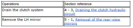
Warning
The clutch master cylinder manufacturer advises against servicing of the clutch master cylinder (1) due to the safetycritical nature of this component. Incorrect overhaul of this component could endanger rider safety.
Maintenance operations of the master cylinder are limited to replacing the following parts: control lever, reservoir unit, and master cylinder fasteners.
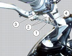
Loosen the special screw (1) by collecting the seals (2), to release the clutch master cylinder assembly (3) from the clutch control pipe (4).
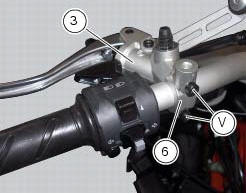
Undo the fixing screws (v) of the mounting u-bolt (6) and then remove the clutch master cylinder unit (3) from the handlebar.
Refer to the exploded view at the beginning of this section for indications on disassembly and replacement of the master cylinder components.
 Hydraulic clutch control
Special screw
Sealing washer
Clutch master cylinder
Clutch hydraulic pipe (metal braid)
Screw
Spare stand
Washer
Microswitch
Pin
Bleed valve
Screw
Roller
O-ring
Clutch ...
 Refitting the clutch master cylinder assembly
Insert the clutch master cylinder assembly (3) and the clamp (6) on the left
handlebar, so that the top mating faces
match the mark (z) on the handlebar as shown.
Couple terminal (6) to th ...
Other materials:
Removal of the rear shock absorber
Loosen the screws (22) and remove the assembly (34) from the frame.
Loosen the screws (27) and remove the tank unit (s) of the shock absorber
from the support (19).
Hold the lh bush (6) and loosen the rh bush (5) to release the front side of
the shock absorber assembly.
Un ...
Check the idle and the co amount with warm engine
Start the engine;
Switch on the dds and check that it does not signal any error (otherwise
consult the relevant paragraph of this manual
to reset the error and proceed with the idle check);
Enter the "self diagnosis" menu by selecting the diavel model in the
available vehicle version. ...
Steering release error - steering still locked
The activation of this (amber yellow) "warning" indicates
that the hands free system was not able to extract the
steering lock.
Warning
In this case, ducati recommends turning the vehicle
off and on (key-off / key-on) holding the handlebar pressed
down to the end stop. If the signal ...