
Ducati Diavel Service Manual: Removal of the shock absorber support
Remove the rear brake master cylinder (sect. 7 - 4, Removing of the rear brake control).
Remove the rear shock absorber (see removal of the rear shock absorber of this section).
Loosen the screws (2) and (7) and their nuts (35).
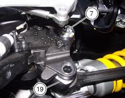
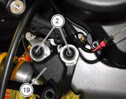
Remove the side stand (sect. 7 - 16, Removing of the side stand).
 Refitting the rear suspension
Lubricate the thread and underside of the special screw (1).
Insert the lower side of the shock absorber into the swingarm and insert the
screw (1).
Tighten the screw (1) to a torque of 45 nm ...
 Refitting the shock absorber support
If you had removed them, apply recommended grease on the threads of the
adjusters (4) and the ring nuts (3) having
care not to have grease on the surface (c) of the adjusters.
Tighten the adjust ...
Other materials:
Refitting the abs control unit
If the brake hoses (7), (8), (9) and (10) on the abs control unit are changed
or removed, ensure that the fittings on the
control unit are positioned correctly.
Warning
If incorrectly positioned, the hose can affect brake operation and
foul moving parts. Position the hose as shown in the
fig ...
Removal of the swingarm
Before removing the parts in question, you must first carry out the following
operations:
Remove the rear wheel eccentric hub as described in chapter "removal of the
rear wheel eccentric hub and rear wheel
shaft" of this section.
Loosen screws (7) and remove the hose grommets (13), (15) ...
Electrical components support
Clip
Screw
Voltage regulator
Battery fixing bracket
Battery support
Vibration damper mount
Hose clip
Vibration damper mount
Clip
Washer
Screw
Cover
Cable grommet
Battery
Battery mat
Screw
Bracket
Solenoid starter
Spring washer
Spacer
Screw
Horn
Scre ...