
Ducati Diavel Service Manual: Removal the airbox and throttle body
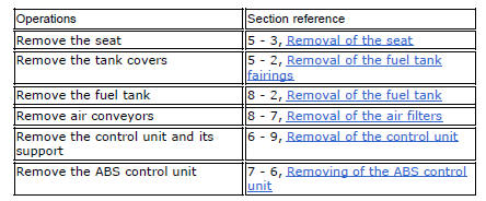
Loosen the screws (a) and remove the plate (b) that fixes the main wiring to the airbox.
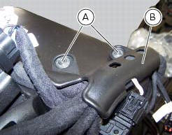
Undo the screws (17) and remove the air pressure sensors (9) with the support (19).
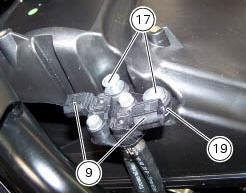
Release the hoses (c) of the air pressure sensors (9) from the tab (d) on the airbox.
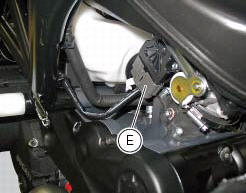
Operating on the right side of the vehicle, disconnect connector (e) from the aps sensor.
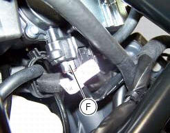
Operate on the vehicle lh side, disconnect connector (f) of the tps/etv motor.
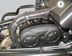
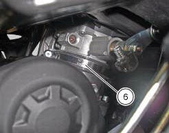
Loosen the clamp (6) that retains the blow-by pipe to the airbox
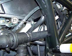
Loosen the clamp (21) that retains the drain hose to the airbox.
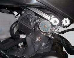
Loosen the clamps (6) that retain the airbox to the intake manifolds, and slide it out of its housing.
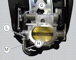
Operating on both throttle grip cables (h) and (m), loosen the nuts (l) and, turning the throttle body pulley (g), slide the two throttle grip cables (h) and (m).
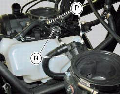
Removal of the fuel injectors
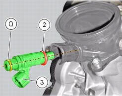
Operating on both intake manifolds, disconnect the connectors (n) that connect the main wiring to the injectors, loosen the fuel pipe retaining screws (p) and slide out the two injectors (3).

Refitting the injectors
Operate on both intake manifolds, check the presence of the o-rings (2) and (q) on injectors (3). Apply prescribed grease on o-rings (2) and (q) of injectors (3).
Insert the injectors in the relevant seats on the intake manifolds.
Important
To avoid damaging the o-rings, insert the injectors fully home on the intake manifolds by keeping them in line with the relevant seat.
Operate on both intake manifolds, position the fuel pipes fittings on the injectors.
Important
To avoid damaging the injectors o-rings insert the fittings by holding them in line with the injectors.
Keep the fittings pressed on the injectors, then start and tighten the screws (p) fully home.
Tighten the retaining screw (p) to a torque of 5 nm +/- 10% (sect. 3 - 3, Frame torque settings).
Connect the main wiring connectors (n) to the injectors.
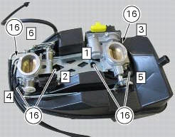
Disassembly of the airbox - throttle body
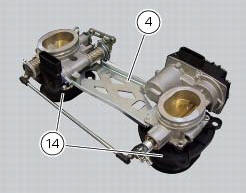
Undo the six screws (16).
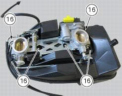
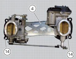
Remove the throttle body (4) from the filter box (1) with the intake manifolds (14).
Reassembly of the airbox - throttle body
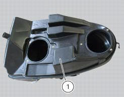
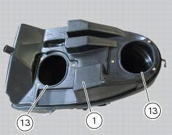
If removed, fit the seals (13) in the seats on the filter housing (1).
Note
To better insert the seals (13) use lubricant specific for rubber.
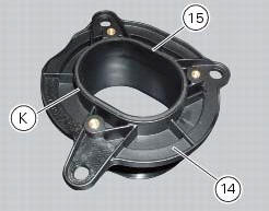
If removed, insert the gaskets (15) in the seats (k) of the intake ducts (26).
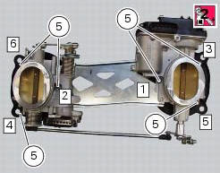
If removed, refit the intake ducts (14) on throttle body (4) and apply prescribed threadlocker to the screws (5) and tighten them to a torque of 3.5 Nm +/- 10% (sect. 3 - 3, Frame torque settings) following the sequence indicated in figure.
Important
After tightening, visually check that the seals (15), previously fitted on the intake funnels, are still in their seats, and that the intake funnels are perfectly coupled with the throttle body.
Fasten the throttle body (4) to the airbox (1).
Position and tighten the fixing screws (16) and tighten them to the torque of 5 nm +/- 10% (sect. 3 - 3, Frame torque settings), following the sequence indicated in figure
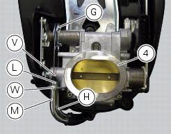
If removed, refit the throttle grip cable as indicated: insert the opening cable (m) and the closing cable (h) in the corresponding plate seats (w) on the throttle body (4) as shown in figure.
Note
The throttle cables are distinguished by the writings in different colours on them:
- On the opening throttle cable is a white writing;
- On the closure throttle cable is a yellow writing.
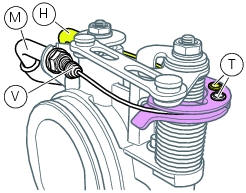
Insert the bolts (t) in the corresponding seats of the pulley. Keep oriented as shown in figure, fasten the cables (m) and (h) inserting the nuts (l).
Tighten the nuts (l) to a torque of 2.5 Nm +/- 10% (sect. 3 - 3, Frame torque settings).
Fit the dust caps (v) on the throttle cable sheaths terminals.
Check that the clip (21) of hose (26) is positioned as shown.
 Airbox - throttle body
Airbox
O-ring
Injector
Throttle body assembly
Screw
Clamp
Intake manifold
Screw
Pressure sensor
Screw
Clamp
Hose
Sealing washer
Intake manifold
Sealing washer
Scre ...
 Refitting the airbox and throttle body
Position the filter box (1).
Operate on the vehicle lh side, connect connector (f) of the tps/div motor.
Operating on the right side of the vehicle, connect connector (e) from the
aps sensor ...
Other materials:
Timing system
Desmodromic (type) with four valves per cylinder,
operated by eight rocker arms (4 opening rockers and 4
closing rockers) and two overhead camshafts. It is operated
by the crankshaft through spur gears, belt rollers and toothed
belts.
Desmodromic timing system (fig. 159)
Opening (or upp ...
Key-on/key-off using the key on the hands free lock with the passive key
Key-on can be performed by pressing the button (7) on the
hands free lock and with the presence of the passive key (4,
fig. 77).
Note
The passive key (4, fig. 77) Has a range of a few cm,
therefore the key (4, fig. 77) Must be positioned near the
antenna (2). Remove the seat (see "remova ...
Engine
Twin cylinder, four-stroke, 90 "l" type, longitudinal, with
deep sump die-cast crankcase.
Bore, mm: 106
Stroke, mm:
67.9
Total displacement, cu. Cm:
1198
Compression ratio:
11.5±0.5:1
Max power at crankshaft (95/1/ec), kw/hp:
119 kw/162 hp at 9,500 rpm
Max torque at crankshaf ...