
Ducati Diavel Service Manual: Refitting the airbox and throttle body
Position the filter box (1).
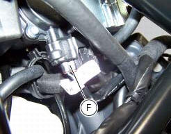
Operate on the vehicle lh side, connect connector (f) of the tps/div motor.
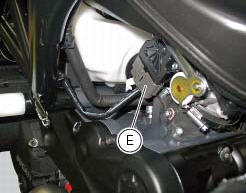
Operating on the right side of the vehicle, connect connector (e) from the aps sensor.
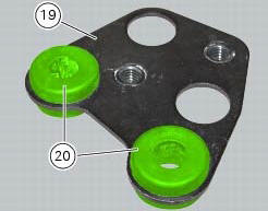
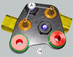
Check for the vibration dampers (20) on the map sensor supporting bracket (19).
Insert the spacers with collar (18) fully home onto the vibration dampers (20).
Note
Two spacers with collar (18) must be fitted on the upper side of the bracket (19) and the other two spacers with collar (18) must be fitted on the lower side of bracket (19).
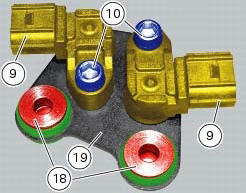
Set the map sensors (9) as shown on bracket (19) and fix them starting the screws (10).
Note
When fitting the map sensors, make sure to insert sensors (a) correctly into their seats in bracket (19) as shown.
Tighten the screws (10) to a torque of 10 nm +/- 10% (sect. 3 - 3, Frame torque settings).
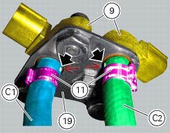
Insert a clip (11) on the longer hose (c1) and a clip (11) on the shorter hose (c2).
Fit the longer hose (c1) and the shorter hose (c2) on the map sensors (9) and position them so as to match the marks on longer hose (c1) and shorter hose (c2) with the arrows on the map sensor supporting bracket (19).
Fix the hoses (c1) and (c2) with the clips (11).
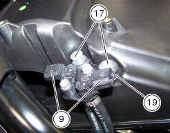
Refit the air pressure sensors (9) with the support (19) by starting and tightening the screws (17) to a torque of 5 nm +/- 10% (sect. 3 - 3, Frame torque settings).
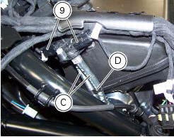
Block the hoses (c) of the air pressure sensors (9) with the tab (d) on the airbox.
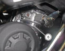
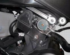
Position and tighten the clamps (6), as indicated, to the torque of 2.5 Nm +/- 10% (sect.3 - 3, Frame torque settings).
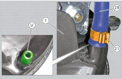
If the drainage pipe has been removed, fit clamp (21) onto drainage pipe (26).
Fit the drainage pipe (26) by inserting it fully home on fitting (u) on the filter box (1).
Orient the clamp (21) as indicated.
Fix the drainage pipe (26) by tightening the clamp (21).
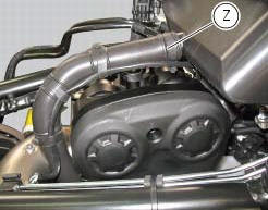
Refit the blow-by pipe to the airbox by tightening the clamp (z) to a torque of 5 +/- 10% (sect. 3 - 3, Frame torque settings).
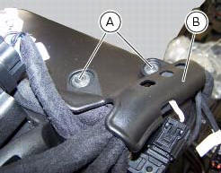
Refit the plate (b) retaining the main wiring to the airbox by tightening the screws (a) to a torque of 5 nm +/- 10% (sect.
3 - 3, Frame torque settings).
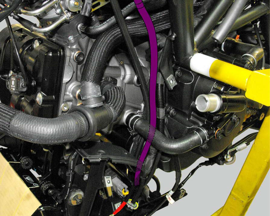
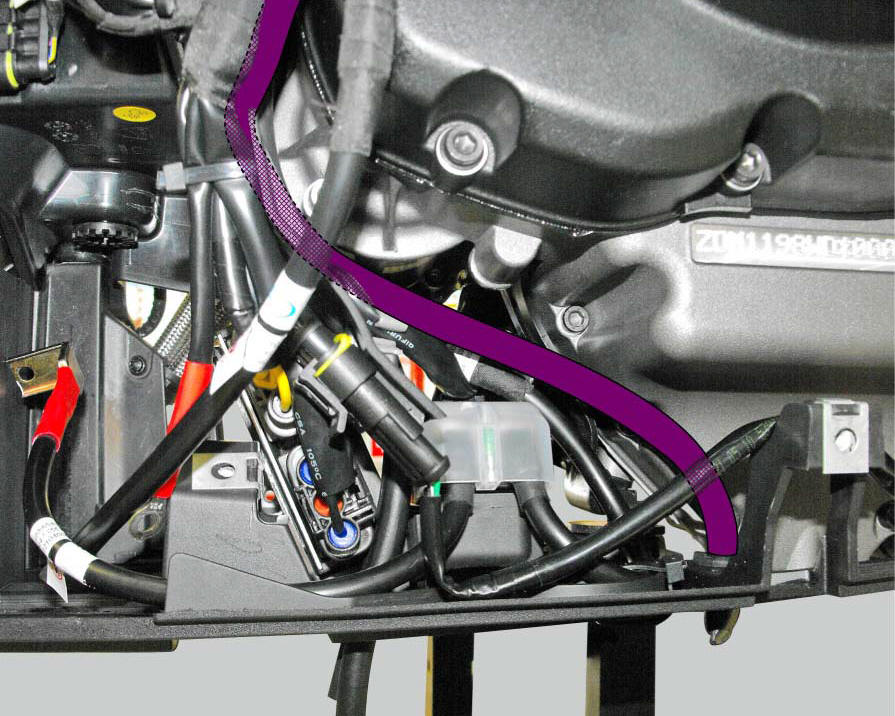
Positioning of the airbox drain hose
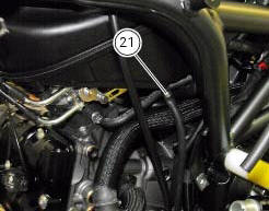
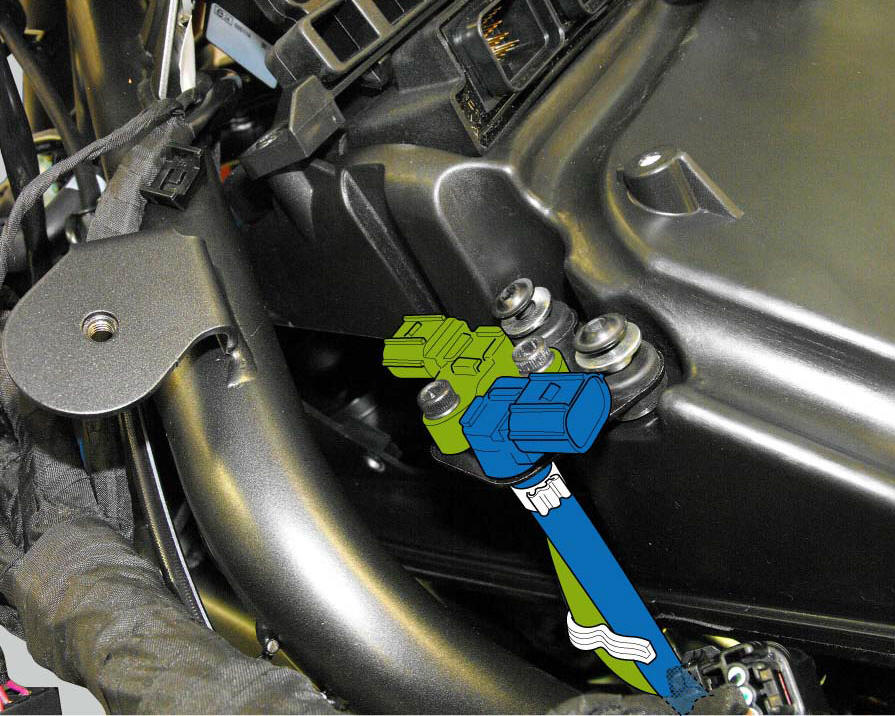
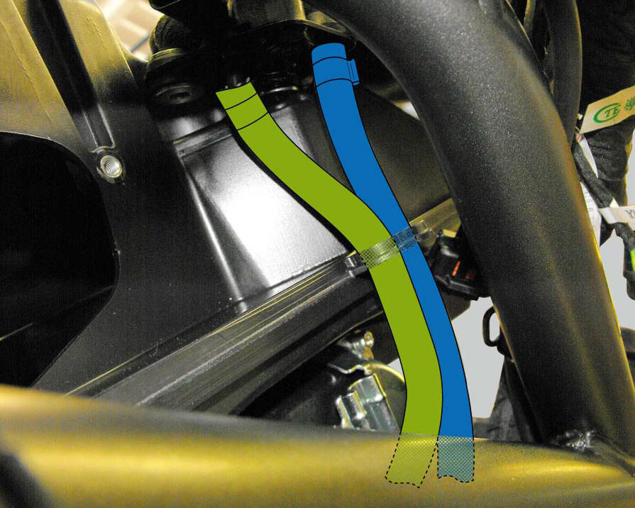
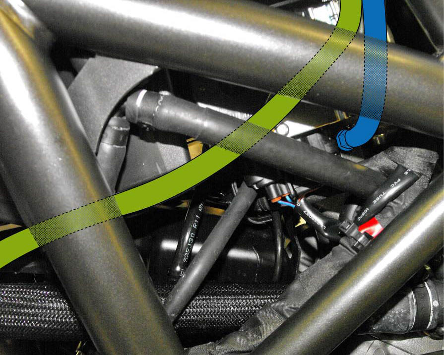
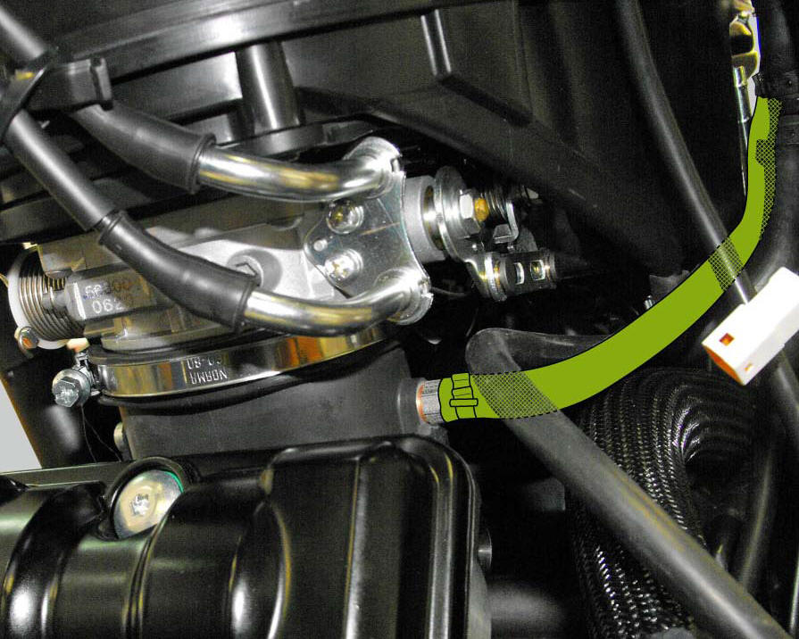
Positioning of the horizontal and vertical head air sensor hoses
 Removal the airbox and throttle body
Loosen the screws (a) and remove the plate (b) that fixes the main wiring to
the airbox.
Undo the screws (17) and remove the air pressure sensors (9) with the support
(19).
Release t ...
 Air intake
Air filter
Right air duct
Screw
Air temperature sensor
Screw
Left air duct
Sealing washer
Threaded insert
Spacer
Clamp
Breather hose
Spare parts catalogue
Diavel abs air ...
Other materials:
Removal of the shock absorber support
Remove the rear brake master cylinder (sect. 7 - 4, Removing of the rear
brake control).
Remove the rear shock absorber (see removal of the rear shock absorber of this
section).
Loosen the screws (2) and (7) and their nuts (35).
Remove the side stand (sect. 7 - 16, Removing of the ...
Replacing the rear phonic wheel sensor
Disconnect the rear abs sensor (5) connector (c) from the main electric
wiring.
Open all the retainer clamps of the rear abs sensor cable (5): refer to table of
sect. 7 - 6, Flexible wiring/hoses
positioning.
Remove the rear abs sensor (5) from its seat on the rear calliper mounting ...
Removal of the cooling system hoses and unions
Loosen the clips (21) that secure the radiator/thermostat sleeve (40) and the
radiator/plug sleeve (24) to the water
radiators.
Loosen clips (25) and (43) that secure the breather pipe (26) to the
radiator/plug sleeve (24) and to the left radiator.
Loosen the clips (34) securi ...