
Ducati Diavel Service Manual: Refitting the abs control unit
If the brake hoses (7), (8), (9) and (10) on the abs control unit are changed or removed, ensure that the fittings on the control unit are positioned correctly.
Warning
If incorrectly positioned, the hose can affect brake operation and foul moving parts. Position the hose as shown in the figure.
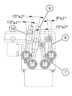
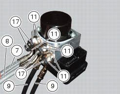
Pipes (7), (8), (9) and (10) fixing must be carried out by placing new gaskets (11) between the couplings.
Tighten the screws (17) to the torque of 23 nm +/- 10% (sect. 3 - 3, Frame torque settings).
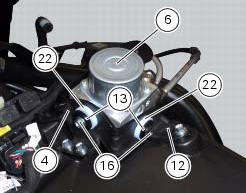
Check that there are vibration dampers (22) and spacers (13) on the abs supporting bracket (12).
Refit the abs control unit (6) on the supporting bracket (12), and fix it by starting and tightening the retaining screws (16) to a torque of 10 nm +/- 10% (sect. 3 - 3, Frame torque settings).
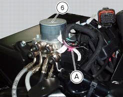
Connect the connector (a) of the abs control unit (6).
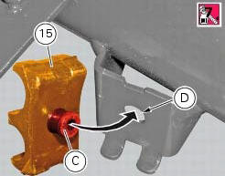
If removed, refit the front rubber pad (15) applying the recommended threadlocker to the pin (c) and the rear face of the pad. Fit the pad inserting pin (c) into the corresponding hole (d).
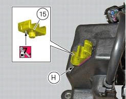
If removed, refit the rear rubber pad (15) applying the recommended threadlocker to the cover of the exhaust valve motor until achieving engagement.
Note
The rubber pad (15) must be aligned with the corresponding reference notch (h) as shown.
To fill up the system, carry out the instructions for replacement of fluid of the front and rear braking system master cylinder or calliper to which the pipe is connected (sect. 4 - 3, Changing the brake fluid).
Important
If the abs control unit is replaced, this must be supplied with secondary circuit already full of fluid; the control unit must Be fitted and the system filled and bleeded as a traditional system.
 Removing of the abs control unit
Drain the hydraulic fluid that is inside the front and rear braking system
tubes by disconnecting them from the master
cylinder and the calliper (sect. 4 -3, Changing the brake fluid).
Disco ...
 Flexible wiring/hoses positioning
The routing of the abs wiring has been optimised to ensure the minimum
obstruction.
Each section is designed to prevent interference with parts that might damage
wires or cause operating failur ...
Other materials:
Parking
Park the stopped motorcycle on the side stand.
Turn the handle completely to the left or right.
If this operation is performed within 60 seconds after the
engine stop, the message "waiting for lock" (fig. 120) Will
appear on the display of the instrument panel for approx.
5 Seco ...
Warning indication (alarms/signals)
The instrument panel activates in real-time some warnings /
malfunction that are not dangerous for the correct operation
of the vehicle.
At key-on (at the end of the check) one or more "warnings"
are displayed if they are active.
When a "warning" is triggered, the indica ...
Overhaul of cylinder head components
Cylinder heads
Remove any carbon deposits from the combustion chamber and its ducts.
Remove any scale from the coolant ducts.
Check for cracking and inspect the sealing surfaces for scoring, ridges or other
damage.
Check that the cylinder barrel mating surfaces of the cylinder head are ...