
Ducati Diavel Owners Manual: Riding mode customisation
This function customises each riding style.
To access the function it is necessary to view the "setting"
menu page 48, using button (1, fig. 14) ?
or (2, fig. 14)
? select the "riding mode" function
and press the
reset button (12, fig. 12) To go to next page.
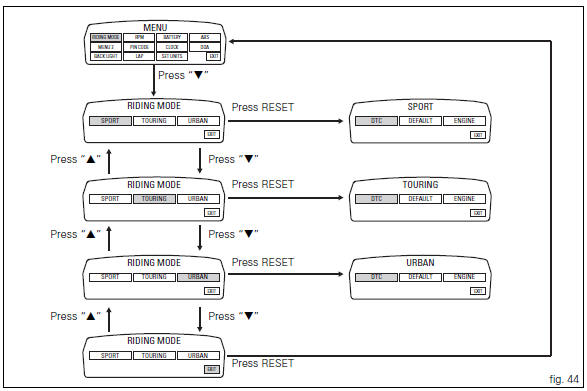
When accessing the function, the three riding modes appear
on the display; to customise the parameters, use button (1,
fig. 14)  or (2, fig. 14)
 to select the riding mode to
be changed and press the reset button (12, fig. 12) To
confirm.
The parameters that can be "customised" are "dtc" (ducati traction control) and "engine".
Any parameter change made is saved in the memory also after a battery-off.
To change the dtc parameters see the "dtc (ducati traction control)" paragraph page 52.
To change the engine parameters see the "engine (engine power control)" paragraph page 56.
The parameters set by ducati for each individual riding style can be restored with the "default" function.
To reset the "default" parameters see the "default (resetting ducati default parameters)" paragraph page 58.
 Note
Note
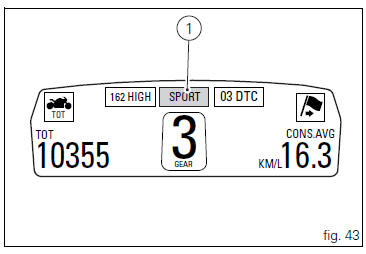
If the parameters have not been modified (customised) or are reset using the "default" function, when you quit the setting menu, in the "main" screen, the "background" indicating the riding style (sport, touring or urban) becomes blue (1, fig. 43).
 Warning
Changes should only be made to the parameters by people who are experts in motorcycle setup; if the parameters are changed accidentally, use the "default" function to reset the parameters.
 Setting menu
This menu is used to enable/disable and set some
motorcycle functions.
To access the "setting menu" press the button (2, fig. 14)
? for 3 seconds.
Note
When within this menu no ...
 Dtc (ducati traction control) setting function
This function allows you to customise the level of dtc
intervention (ducati traction control) or disable it for every
riding mode.
To access the function it is necessary to view the "setting ...
Other materials:
Tester power supply
The dds (1) part number 97900.0215 Can be powered from the vehicle as
follows:
From the mains power supply: by connecting the power supply connector
(n) to the network power supply (2) part no.
97900.0224;
From the motorcycle: connecting the corresponding cables (see paragraph
...
Residual range indication when the service is due
After resetting the first oil service warning (triggered at 1000 km), upon
every key-on the system displays the
indication of which type of service should be performed next (oil service or
desmo service) and the residual range.
A (green) warning (1) is activated for 2 seconds on every key-on ...
Removal of the swingarm
Before removing the parts in question, you must first carry out the following
operations:
Remove the rear wheel eccentric hub as described in chapter "removal of the
rear wheel eccentric hub and rear wheel
shaft" of this section.
Loosen screws (7) and remove the hose grommets (13), (15) ...