
Ducati Diavel Service Manual: Steering angle adjustment
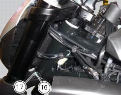
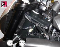
Loosen the nuts (17) and adjuster screws (16) on both sides of the bottom yoke.
Use a 6 to 6.5 Mm spacer (a) fitted to the fork outer tube, or use a gauge.
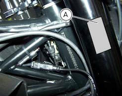
Turn the front forks to the right until the spacer (a) is seated against the frame top tube.
Tighten the adjuster screw (16) to bring it into contact with the stop on the steering head.
Apply threadlocker to the thread of nut (17). Hold the adjuster screw (16) firm and tighten the nut (17). Turn the forks to the opposite side: and repeat the process to adjust the other dowel and tighten the relative lock nut.
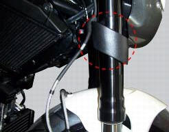
Once adjusted, set handlebar completely turned right and ensure that the gap between front brake line and lower frame trellis is at least 1 mm. If it is not so, decrease steering angle by working the right-hand adjuster.
 Adjusting the steering head bearings
Note
To adjust the steering bearing clearance, follow what is described in
sect. 4 - 3, Adjusting the steering head bearings.
If the problems found are not solved, check the wear of steering beari ...
 Removal of the steering head components
Note
All parts fitted to the top and bottom yokes, including the wiring and
control cables, can remain on the motorcycle
provided they do not hinder the following operations.
Loosen the screw ...
Other materials:
Checking the camshafts and supports
Check the cam contact surfaces for scratches, grooves, steps and waving.
Worn cams are frequently the cause of poor timing, which leads to loss of engine
power.
Place the camshaft between two centres and check the run-out on the areas
indicated using two dial gauges.
Service limit: 0.1 ...
Fuel, lubricants and other fluids
Important
Do not use additives in fuel or lubricants.
Engine oil
A good quality engine oil has special properties. Use only a highly detergent
engine oil with certified se, sf or sg or
higher service ratings as marked on the container.
Viscosity
Sae 15w-50
The other viscosity grades ...
Valves - rocker arms
Closing rocker arm shaft
Opening rocker arm shaft
Opening rocker arm
Closing rocker arm (left)
Valve opening shim
Half rings
Valve closing shim
Sealing ring
Valve guide
Exhaust valve seat
Exhaust valve
Plug
Intake valve seat
Intake valve
Aluminium gasket
Closing ...