
Ducati Diavel Service Manual: Removal of the rear brake calliper
Important
The brake manufacturer advises against any servicing of the internal components of brake callipers or the master cylinder.
Incorrect overhaul of these critical safety components can endanger rider and passenger safety.
Before removing the parts in question, you must first carry out the following operations:
note
For the abs front braking system, also refer to sect. 7 - 5, Abs system operating information, sect. 7 - 6, System components, sect. 7 - 7, Abs components maintenance.
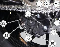
Unscrew and remove the special screw (22) fixing the pipes (33) to the rear brake calliper and the corresponding couplings (23).
Remove tube (33).
Undo the two fixing screws (12) of the rear brake calliper (15) to the calliper holder bracket and remove the brake calliper (15).
If it is necessary to remove the calliper holder bracket (a) refer to sec. 7 - 13, Removal of the rear wheel eccentric hub and rear wheel shaft.
Note
To replace the brake pads follow instructions in the paragraph "checking brake pad wear and changing brake pads" (sec. 4 - 3).
To remove the speed sensor (1), undo the retaining screw (2), having care not to damage the airgap spacer (8) and the washer (32).
Only the following parts should be renewed:
- Brake calliper: pads, fasteners and bleed valve assembly;
- Master cylinder: control pedal, bleed valve assembly, reservoir and its components.
Refer to the exploded view at the beginning of this section for indications on renewal of the above components.
 Refitting the rear brake control
If the pushrod (18), clip (30) and fork (31) assembly has been dismantled,
reassemble it by screwing the nut (29) onto
the rod (18) and then screw the rod into the fork (31) to obtain the measureme ...
 Removal of the rear brake disc
Remove the rear eccentric hub (sec. 7 - 13, Removal of the rear wheel
eccentric hub and rear wheel shaft).
Undo and remove the four fixing screws (13) of the brake disk to the wheel axle
and re ...
Other materials:
Removal of the cylinder heads
Using the tool code 88713.2676, Undo the nuts (21) on the cylinder head stud
bolts.
Remove the cylinder head nuts (21) and special washers (22).
Remove the cylinder head assembly by lifting it off the engine studs.
Repeat the same procedure for the other cylinder head. ...
Overhaul of the crankcase halves
Carefully examine the engine crankcase halves.
Check that the surfaces of the crankcase halves are perfectly flat using a
reference surface.
Check that the bearings (1) and (18), and the bushings (2) and (17) are in
optimum conditions. Note that the main
bearings must always be changed in p ...
Low hands free key (hf) battery level
The activation of this (amber yellow) "warning" indicates that the hands free
system has detected that the battery that
permits the active key (a) to communicate and turn the vehicle on is almost
discharged.
Note
In this case replace as soon as possible the battery as indicated in sect.
6 - ...