
Ducati Diavel Service Manual: Abs fault indicator not working
Fault codes
Dds: displays a fault code described in the description of the abs system.
Dashboard: no fault code displayed.
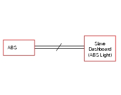
Wiring diagram
Checks
The abs fault indicator indicates the occurrence of one or more faults in the antilock brake system, or if the system itself has been disabled by the rider, using the relative control. The signal causing activation of the abs fault indicator in the event of an antilock brake system malfunction, comes directly from the abs control unit, and the information is transmitted over the can line, so that it may be acquired by the dashboard, where the indicator itself is located.
Diagnose the abs unit.
Check the integrity of the electrical circuit and connections (short-circuits to ground, short-circuits to vdc, open circuits).
If the above test did not identify the problem, contact ducati.
Note
Check integrity of electric circuit - short-circuit to vdc = with dashboard on, using a voltmeter, a voltage is measured between the wire tested and ground check integrity of electric circuit - short-circuit to ground = with the battery cables disconnected, using an ohmmeter, continuity is detected between the wire tested and ground check integrity of electric circuit - open circuit = with the battery cables disconnected, using an ohmmeter, no continuity is detected between the two ends of the wire tested)
 Dashes shown instead of speed indication or indicated speed is incorrect
Fault codes
Dds: speed sensor diagnosis -> max. Speed (max. Speed error - signal not
correct) - minimum speed (min speed error -
signal not correct) - congruence (correlation speed error - sign ...
 Abs disabled information not displayed
Fault codes
Dds: displays a fault code described in the description of the abs system.
Dashboard: no fault code displayed.
Wiring diagram
Checks
The abs fault indicator indicates the occurr ...
Other materials:
Specific operating strategies
Idle speed
No electric motor is used for idle speed regulation (bypass is modulated
instead with the throttle valve), as idle speed
control is effected by the ride-by-wire system. Idle speed is maintained by the
control unit when the speed drops below a
specific threshold and when the clutch ...
Adjusting the position of the gear change and rear brake pedals
The position of the gear change and rear brake pedals in relation to the
footrests can be adjusted to suit the preferred
riding position.
To modify the gear change pedal position act in the following mode:
hold the linkage (1) and slacken the counter nuts (2) and (3).
Note
Nut (2) has a lef ...
Overhauling the front wheel
Wheel bearings
Before checking the dimensions, check the wear on wheel bearings. Check for
wear by hand after cleaning and degreasing
the bearings in their seats.
Turn the inner race.
Check the amount of radial and axial play. Excessive play will cause vibration
and make the bike unstabl ...