
Ducati Diavel Service Manual: Removing of the rear brake control
Warning
The brake master cylinder manufacturer advises against servicing the brake master cylinder due to the safety critical nature of this component.
Incorrect overhaul can endanger the rider and passenger.
Maintenance operations on these units are limited to renewal of the following parts: control lever, fluid reservoir assembly and relative fasteners and master cylinder fasteners.
Note
For the abs front braking system, also refer to sect. 7 - 5, Abs system operating information, sect. 7 - 6, System components, sect. 7 - 7, Abs components maintenance.
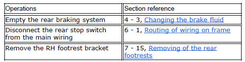
Slide the adjusting rod (18) out of the rear brake master cylinder (16).
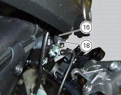
Loosen the special screw (22) from the master cylinder (16); slide out the hose (7) and recover the sealing washers (23).
Loosen the rear brake master cylinder (16) retaining screws (19) and remove it from the vehicle.
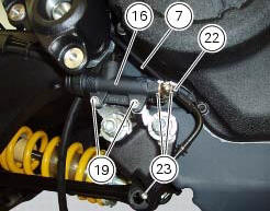
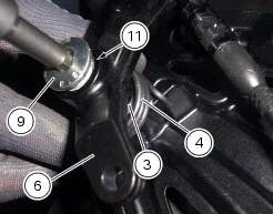
Undo the fixing pin (9) of the brake lever (6), collecting the spring (4).
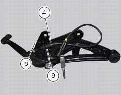
Remove the brake lever (6) and collect the pin (9), the washer (3), the bush (10) and the o-ring (11).
 Rear brake
Rear speed sensor (abs)
Screw
Washer
Spring
Brake switch (rear)
Brake lever (rear)
Rear pump - control unit pipe
Sealing washer
Pin
Bush
O-ring
Screw
screw
Rear brake ...
 Disassembly of the rear brake control
The brake master cylinder is supplied only as a complete unit; internal
components cannot be replaced.
To disassemble the master cylinder's outer parts, follow the indications given
in the expl ...
Other materials:
Programming/reprogramming keys
The dds diagnosis instrument is required in order to programme/reprogramme
the keys. The key programming procedure
is launched from this instrument.
To start the key programming/reprogramming procedure it is necessary to have at
least one of the keys that start the
vehicle available (i.E. I ...
Symbols
Ducati motor holding s.P.A. Advises you to read this manual
carefully in order to become familiar with your motorcycle. If
in doubt, please contact a ducati dealer or authorised
service centre. The information contained herein will prove
useful on your trips - and ducati motor holding s.P.A. Wis ...
Reassembly of the front half-fairings
Fit the clips (2) on the front rh half-fairing (1).
Join the rh support (4) and the front rh half-fairing (1) and keep them in
position by starting the screws (5).
Note
To mount the rh support (4) in a proper way, it is necessary to insert the
tab (g) of the front rh half-fairing (1) in t ...