
Ducati Diavel Service Manual: Abs system operating information
The response of the system is based on the analysis of the speed signals for front and rear wheels; the system is automatically deactivated if either of these signals is missing.
Note
In the event of the abs control unit detecting a fault in the abs electronic management system, it activates the specific fault warning indicator on the dashboard and restores conventional braking functionality without abs.
Hydraulic faults in the brake system and faults not directly related to the abs system (e.G.: Worn brake pads) cannot be detected by the abs control unit.
Important
The response of the system is based on the values read for the front and rear wheel speeds; take great care not to damage the phonic wheels and relative speed sensors when removing the wheels or when working in the vicinity of these components; damage to the phonic wheels damages may compromise the operation of the system and cause dangerous malfunctions.
Abs diagnosis
The diagnostic function of the abs 8m ascertains the functionality of the main system components via hardware/software tests, but cannot modify the operating parameters of the abs system. The dds diagnostic instrument is connected by cable to the abs control unit communication link connector (a), located beneath the saddle. The connection cable between the tester and the abs control unit has another branch with a negative and a positive clamp that must be connected to the vehicle battery to power the tester itself and enable communication with the abs control unit.
From the self-diagnosis menu of the dds instrument, select the abs system model and wait until the correct configuration loads for analysing the configuration of the vehicle. After switching the vehicle to key-on state, the tester communicates with the abs control unit.
Once in this configuration, a number of parameters and states relative to the abs control unit and information concerning the control unit itself may be selected and displayed.
If the tester receives notification from the abs control unit that there are diagnostic errors dating from a prior test session still stored in its memory, the user is warned by specific message on the display and an audible alarm.
The abs control unit identification number, identified by the prefix id ecu, may be viewed from the info menu.
Select the function "view parameters and states"
This function allows the tester to display the following abs system parameters and states:
Viewable parameters 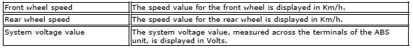
Viewable states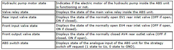
Select the function "view errors"
This tester function provided the user with information concerning the error list in the abs control unit memory, indicating if errors have been stored previously stored or if they are current. The following codes are given after a short description of the diagnosis type: mem, indicating that the error has been stored previously by the abs control unit but has not been detected in the current test session. Att, indicating that the error is current and has been detected during the current test session.
Note
While att indicates that the error has been diagnosed during the current test session, it does not necessarily indicate that the error is actually active at the time of indication. For example: disconnecting the front wheel speed sensor causes the code att to be displayed after the error description, but the code continues to be displayed even once the cause of its activation has been eliminated by reconnecting the sensor, as the abs will only check sensor operation again after the next key-off/key-on cycle. As a result, always perform a key-on/key-off cycle after any work on the abs system, interrupting and reopening communication between the diagnostic instrument and the abs control unit before checking The updated abs error list again.
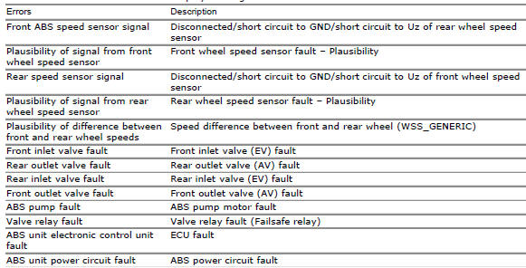
The abbreviations for all the errors displayed are given as follows:
Select the function "abs system information"
This tester function displays the identification data for the abs system, such as supplier reference, software version and barcode.
E.G.: Supplier ref.: Ducm696
Software version: 67890
Bar code data: hqojm98200ra
 Operating principle
The ducati abs brake system manages the front and rear brakes separately. A
pulse generator (phonic wheel), with a
ring of slots, is fixed onto each wheel. On the left calliper mounting bracket
o ...
 Abs system deactivation
Carry out the procedure described in section sec. 6 - 7, Abs disabling
function.
Warning
If the vehicle front wheel remains off the ground for a prolonged
period while the vehicle is in motion, ...
Other materials:
How to switch the dashboard on
The dashboard may switched on either from the on/off switch on the handlebar
or from the button on the hands free
system.
With the engine off, the on/off switch is turned to "run off".
With the motorcycle and dashboard off, the on/off switch is turned to "run
off".
To switch the dash ...
Start procedure with pin code (no keys)
The motorcycle may be started without keys with a special procedure using the
dashboard and the switches on the
handlebar.
Note
This procedure is only possible if the pin code has been enabled
previously. For security reasons, the pin code is disabled
by default when the vehicle leaves the f ...
Gearbox shafts
Shim, thickness 1
Gearbox primary shaft
Shim, thickness 0.5
Needle roller bearing
5Th speed driving gear
Splined washer, thickness 0.5
Circlip
3Rd- 4th speed driving gear
6Th speed driving gear
2Nd speed driving gear
Shim, thickness 1.8
Splined washer, thickness 0.5
Sp ...