
Ducati Diavel Service Manual: Adjusting the rear shock absorber
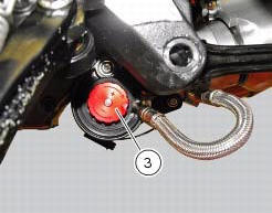
The adjuster (1) located on the lower connection holding the shock absorber to the swingarm adjusts the damping during the rebound phase (return).
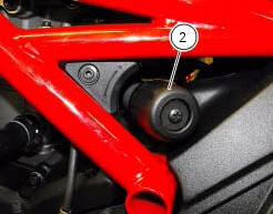
The knob (2), located on the left side of the motorcycle, adjusts the preload of the shock absorber external spring.
Turn the adjuster (1) clockwise to increase damping h; or counter clockwise to reduce damping s.
Standard setting from the fully closed position (clockwise): -unscrew adjuster (1) by 8 clicks.
Spring preload: 15 mm.
The two nuts (2) on the upper part of the shock absorber serve to adjust the preload on the external spring. To change spring preload, slacken the upper locking ring nut. Then tighten or slacken the lower ring nut to increase or decrease spring preload.
Important
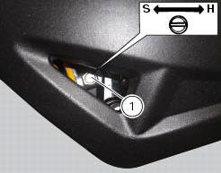
The knob (3) located on the expansion reservoir of the shock absorber adjusts the damping during the compression phase.
Turning the adjusters (1) or the knobs (2) and (3) clockwise to increase preload damping; they decrease turning them in the opposite direction.
Standard setting: from fully closed (clockwise) loosen: register (1) of 12 clicks; knob (2) fully open (counter clockwise); register (3) of 25 clicks.
Spring preload: 18 mm (max.18 Mm - min.25 Mm
Warning
The shock absorber is filled with high-pressure gas and can cause injuries if inexpertly dismantled.
Important
If the motorcycle is to be ridden with a pillion rider and luggage, we
recommend setting the rear shock absorber spring
preload to the maximum to ensure the best handling and proper ground clearance
at all times. It may also be necessary
to adjust the rebound damping accordingly.
 Adjusting the front fork
The front fork used on this motorcycle has rebound, compression and spring
preload adjustment.
This adjustment is done using the outer adjusters:
Rebound damping;
Inner spring preload;
Co ...
 Fairings
...
Other materials:
Reassembly of the crankcase halves
If removed, apply threadlocker on the screw (36), insert it with the washer
(37) on the crankcase half and tighten it to The torque of 8 nm
(min. 7 Nm - max. 9 Nm) (sect. 3 - 3, Engine torque settings).
If removed, apply threadlocker on the dowel thread (35), tighten it to a
torque of 20 ...
Injection and ignition
Introduction
Ignition is via a single stick coil per cylinder installed in the spark plug
well. Each thermal unit is supplied by a single
injector, placed under the throttle valve. The amount of fuel injected and the
ignition advances are determined by the
control unit specifically for each c ...
Disassembly of the rear brake control
The brake master cylinder is supplied only as a complete unit; internal
components cannot be replaced.
To disassemble the master cylinder's outer parts, follow the indications given
in the exploded view at the beginning of this
section.
If the bush (10) inside the brake pedal (6) needs to ...