
Ducati Diavel Service Manual: System components
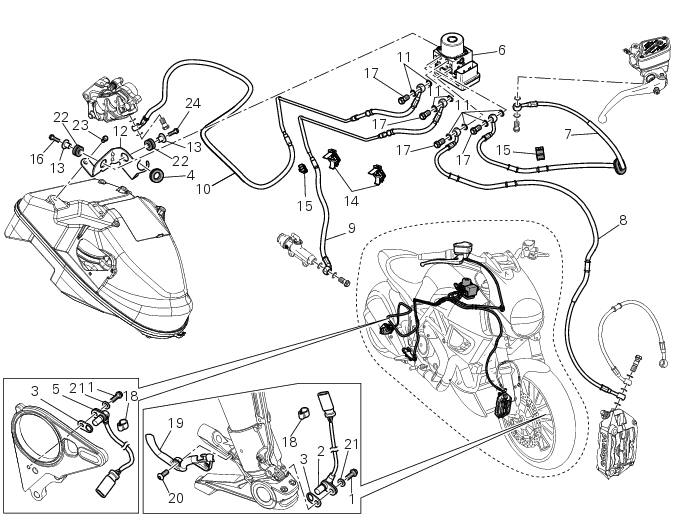
- Screw
- Abs front speed sensor
- Sealing washer
- Hose grommet
- Abs rear speed sensor
- Abs control unit
- Front pump - control unit pipe
- Control unit - front callipers pipe
- Rear pump - control unit pipe
- Control unit - rear calliper pipe
- Sealing washer
- Support
- Spacer
- Rubber mounting
- Screw
- Special screw
- Cable grommet
- cable grommet
- Screw
- Washer
- Vibration damper mount
- Screw
- screw
Spare parts catalogue
Diavel abs antilock braking system (abs)
Diavel carbon abs antilock braking system (abs)
Important
Bold reference numbers in this section identify parts not shown in the figures alongside the text, but which can be found in the exploded view diagram.
- Replacing the front phonic wheel sensor
- Replacing the rear phonic wheel sensor
- Removing of the abs control unit
- Refitting the abs control unit
- Flexible wiring/hoses positioning
 Abs system deactivation
Carry out the procedure described in section sec. 6 - 7, Abs disabling
function.
Warning
If the vehicle front wheel remains off the ground for a prolonged
period while the vehicle is in motion, ...
 Replacing the front phonic wheel sensor
Disconnect the front abs sensor (2) connector (a) from the main electric
wiring.
Open all the retainer clamps of the front abs sensor cable (2): refer to table
of sect. 7 - 6, Flexible wiri ...
Other materials:
Instrument panel (dashboard)
The vehicle is equipped with two instrument panels: an lcd
(1, fig. 3) Located on the handlebar containing the key
indications (speed, rpm, coolant temperature and clock) and
a tft colour display (2, fig. 3) Located in the tank fairing
displaying trip information (riding style set, odometer,
co ...
Removal of the front brake master cylinder
Warning
The brake master cylinder manufacturer advises against servicing the
brake master cylinder due to the safety critical
nature of this component. Incorrect overhaul of these critical safety components
can endanger rider and passenger safety.
Maintenance operations on these units are l ...
Passive key
Introduction
The passive key (1) is used when the active key is not working correctly or
is not available.
The passive key works as a transponder, and must therefore be placed physically
onto the antenna to work.
The mechanical part (2) of the key is used to open the seat or the tank plug ...