
Ducati Diavel Service Manual: Battery
Battery safety rules
Warning
Before carrying out any operations on the battery, keep in mind the safety standards (sect. 1 - 3, General safety rules).
When under charge, batteries produce explosive gases. Keep batteries away from heat sources, sparks or open flames.
Instructions for use
The battery is a sealed, maintenance-free type and therefore requires no servicing installation.
Note
Always keep the battery clean. Apply grease around the battery terminal clamps to prevent corrosion.
Warning
Never remove the valve cover located on top of the cover. If the block, cover or terminals are broken or if the valve cover has been tampered with it is absolutely necessary to replace the battery.
Important
If the motorcycle is left unused for more than 30 days, remove the battery and store it in a safe, cool place.
Always charge the battery before the first operation and after long storage periods - such as before selling the vehicle.
Removal of the battery 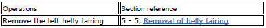
undo the screws (1) and remove the battery retaining bracket (2).
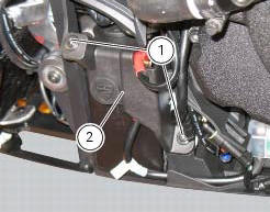
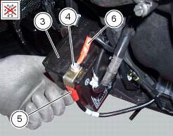
Slide out the battery (3) from its housing and, always starting from the negative terminal (-), loosen the screws (4).
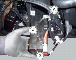
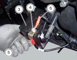
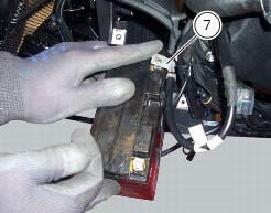
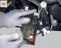
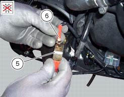
Remove the positive cable (5), the abs positive cable (6) from the positive terminal, and the negative cable (7) from the negative terminal.
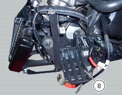
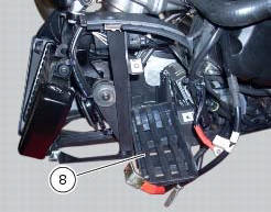
Remove the battery drift (6) on the battery support (7).
Refitting the battery
Position the battery drift (6) on the battery support (7).
Place the battery (3) in its compartment by connecting first cable (7) to the negative terminal with the screw (4).
Connect the positive cable (5) and then the abs positive cable (6) to the positive terminal with the screw (4).
Tighten the terminal screws (4) to a torque of 10 nm +/- 10% (sect. 3 - 3Frame torque settings) and apply grease around the battery terminal clamps to prevent oxidation.
Place the battery (3) on its support, then position the retaining bracket (2) and tighten the screws (1) to a torque of 10 nm +/- 10% (sect. 3 - 3, Frame torque settings).

 Topping up the electrolyte
Warning
Before carrying out any operations on the battery, keep in mind the
safety standards (sect.1 - 3, General safety rules).
The electrolyte in the battery is toxic and can cause burns if it ...
 Alternator
It is equipped with a 12 v, 430 w generator, consisting of a fixed element
(stator, a) located on the generator cover and
of a movable element (rotor, b) fixed to the crankshaft.
Note
To chec ...
Other materials:
Gear change pedal
When released, the gear change pedal (1, fig. 96)
Automatically returns to rest position n in the centre. This is
indicated by the instrument panel light n (2, fig. 4) Coming on.
The pedal can be moved:
down = press down the pedal to engage the 1st gear and to
shift down. At this point the n ...
Refitting the tail light
Fit the spacers with collar (3) into the rear vibration dampers (2) located
on the gloves compartment (23).
Note
Two spacers (3) must be inserted inside and outside on the right side and
two spacers (3) must be inserted inside and
outside on the left side.
Insert the split vibration damp ...
Battery voltage indicator (battery)
This function describes the battery voltage indicator.
To access the function it is necessary to view the ""setting" menu", using
buttons (1) "s" or (2) "t" select the "battery"
function and press the reset button (3) to confirm.
The information will be displayed as follows:
if battery vol ...