
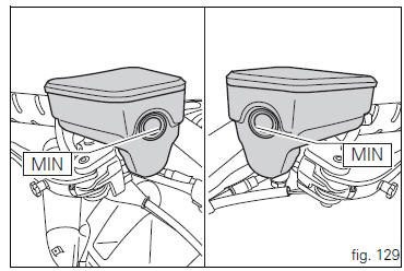
Ducati Diavel Owners Manual: Checking brake and clutch fluid level
The levels should not fall below the min marks on the respective reservoirs.
If the level is too low, air can get into the circuit, thus impairing the efficiency of the system.
Brake and clutch fluid must be topped up and changed at the intervals specified in the scheduled maintenance table reported in the warranty booklet; please contact a ducati dealer or authorised service centre.
 Important
It is recommended all brake and clutch lines be changed every four years.
Brake system
If you find exceeding play on brake lever or pedal and brake pads are still in good condition, contact your ducati dealer or authorised service centre to have the system inspected and any air drained out of the circuit.
 Warning
Brake and clutch fluid can damage paintwork and plastic parts, so avoid contact. Hydraulic fluid is corrosive and can cause damage and injuries. Never mix fluids of different qualities.
Check that the seals are in good condition.
Clutch system
If the control lever has exceeding play and the transmission snatches or jams as you try to engage a gear, it means that there might be air in the circuit. Contact your ducati dealer or authorised service centre to have the system inspected and air drained out.
 Warning
The clutch fluid level in the reservoir tends to rise as the friction material on the clutch plates wears out. Do not exceed the specified level (3 mm above the minimum level).
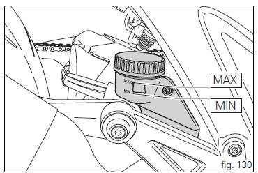
 Checking and topping up coolant level
Check coolant level in the expansion tank on the right side of
the vehicle.
Steer the handlebar completely to the left and check that the
level is between the min and max marks on the side of the ...
 Checking brake pads for wear
Check brake pads wear through the inspection hole in the
callipers.
Change both pads if friction material thickness of even just
one pad is about 1 mm.
Warning
Friction material wear beyond th ...
Other materials:
Solenoid starter
Remove the protection cover (a).
Undo the screws (2), taking care to collect the spring washers (3).
Remove the starter motor-solenoid cable (4) and the solenoid-battery cable (5).
Remove the starter solenoid (1) sliding it upwards.
Checking operation of the starter solenoid
To ...
Checking brake pads for wear
Check brake pads wear through the inspection hole in the
callipers.
Change both pads if friction material thickness of even just
one pad is about 1 mm.
Warning
Friction material wear beyond this limit would lead to
metal support contact with the brake disc thus
compromising braking efficie ...
Electrical components support
Clip
Screw
Voltage regulator
Battery fixing bracket
Battery support
Vibration damper mount
Hose clip
Vibration damper mount
Clip
Washer
Screw
Cover
Cable grommet
Battery
Battery mat
Screw
Bracket
Solenoid starter
Spring washer
Spacer
Screw
Horn
Scre ...