
Ducati Diavel Service Manual: Rear shock absorber assembly
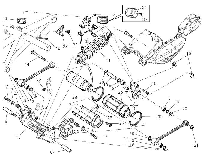
- Special screw
- Screw
- Nut
- Grub screw
- Bush (right)
- Bush (left)
- Screw
- Sealing ring
- Roller bearing
- Linkage (left)
- Shock absorber (rear)
- Linkage (right)
- Spacer
- Special screw
- Screw
- Bush
- Ball joint
- Rocker arm assembly
- Support
- Washer
- Nut
- Screw
- Shock absorber adjuster support
- Screw
- Support
- Rubber pad
- Screw
- Clamp
- Plate
- Screw
- Hose clip
- Washer
- Screw
- Knob
- Nut
- Grub screw
- Screw
Spare parts catalogue
Diavel abs rear suspension
Diavel carbon abs rear suspension
Important
Bold reference numbers in this section identify parts not shown in the figures alongside the text, but which can be found in the exploded view diagram.
Rear suspension system
The rear suspension system uses a hydraulic mono-shock absorber (11) with rebound and spring preload adjustment.
This system consists of a rocker arm (18) and two linkages (10) and (12) fixed to the swingarm and the engine.
The shock absorber is pivot-mounted to the swingarm at the lower end and to the engine at the upper end. This system gives the motorcycle excellent stability.
To adjust the rear shock absorber refer to sect. 4 - 3, Adjusting the rear shock absorber.
- Removal of the rear shock absorber
- Disassembly of rear shock absorber - rocker arm - linkage assembly
- Reassembly of rear shock absorber - rocker arm - linkage assembly
- Refitting the rear suspension
- Removal of the shock absorber support
- Refitting the shock absorber support
 Refitting the steering head components
Important
The steering tube bearings (6) are identical but in no case may their
components be swapped around during reassembly.
Clean all contact surfaces and lubricate with the recommended grease ...
 Removal of the rear shock absorber
Loosen the screws (22) and remove the assembly (34) from the frame.
Loosen the screws (27) and remove the tank unit (s) of the shock absorber
from the support (19).
Hold the lh bush (6 ...
Other materials:
Tips for use on the road
Activate the dtc, select level 8 and ride the motorcycle in
your usual style; if the level of dtc intervention seems
excessive, try reducing the setting to levels 7, 6, etc., Until
you find the level that suits you best.
If changes in the grip conditions and/or circuit characteristics
and/or ...
General safety rules
Carbon monoxide
When a maintenance operation must be performed with the engine running, maker
sure that the working area is wellventilated.
Never run the engine in an enclosed space.
Warning
Exhaust fumes contain carbon monoxide, which is a poisonous gas that
can cause unconsciousness or e ...
Refitting the cylinder heads pulleys/fixed tensioners
Check that the keyway on the end of the camshaft is in good condition and
without burrs.
Fit a woodruff key (b) in the keyway of each camshaft.
Fit the pulley (11) on the camshaft, inserting the woodruff key in the in the
slot (c) in the pulley.
Apply the recommended grease to the t ...