
Ducati Diavel Service Manual: Removal of the steering head components
Note
All parts fitted to the top and bottom yokes, including the wiring and control cables, can remain on the motorcycle provided they do not hinder the following operations.
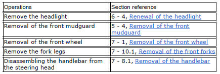
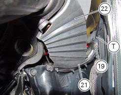
Loosen the screws (19) securing the supports (21) and (23) of splashguard (22) to the air conveyors (t).
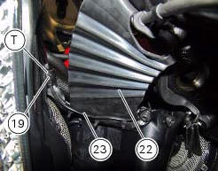
Loosen the screws (19) securing the front support (24) of the splashguard (22) to the bottom yoke (15).
Loosen the screws (v) to free the cable grommets (p) from the steering head (2).
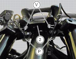
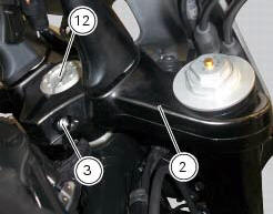
Loosen the screw (3) securing the steering head (2) to the steering head nut (12).
Remove the steering head (2).
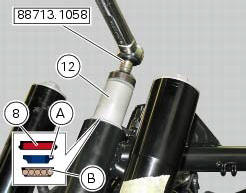
With the service tool no. 88713.1058 Loosen the nut (12) and unscrew it from the steering shaft.
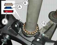
Slide the seal (8), the inner ring (a) and the ball race (b) of the upper bearing (6) off the steering shaft.
Remove the bottom yoke (15) complete with the steering shaft from the frame tube.
Remove the ball race (b) of the lower bearing (6).
The inner race (a) of the lower bearing (6) and the relative oil seal (8) will remain on the steering shaft.
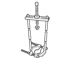
Using a universal puller (see figure) remove the inner race (a) and the spacer (13) from the steering shaft, taking care not to damage the seat.
Important
Once removed, the seals (8) and the bearings (6) must not be refitted.
Using a suitable punch, remove the outer bearing races (c) from the steering head. Proceed with extreme care to avoid damaging the seats.
Disassembly of the steering head
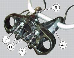
Loosen and remove the screws (7), washers (11) and the lower u-bolts (4) and (5) from the steering head.
Reassembly of the steering head
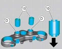
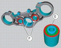
If the spacers (10) were removed from the steering head, lubricate with silicone spray.
Seat the spacers (10) square in the bores (d) in the steering head, orienting them as shown in the figure.
Important
To drive in the spacers (10), use a drift that bears only on the outer ring (e) while applying a counterforce on zone (f) on the underside of the steering head.
On completion of the operation, clean all excess lubricant from the components.
Locate the lower u-bolts (4) and (5) on the steering head.
Fit the screws (7) complete with the washers (11 in the lower u-bolts (4) and (5).
Tighten the screws (7) to a torque of 45 nm +/-5% (sect. 3 - 3, Frame torque settings).

 Steering angle adjustment
Loosen the nuts (17) and adjuster screws (16) on both sides of the bottom
yoke.
Use a 6 to 6.5 Mm spacer (a) fitted to the fork outer tube, or use a gauge.
Turn the front forks to the righ ...
 Refitting the steering head components
Important
The steering tube bearings (6) are identical but in no case may their
components be swapped around during reassembly.
Clean all contact surfaces and lubricate with the recommended grease ...
Other materials:
Instrument panel diagnosis
This function identifies any abnormal vehicle behaviours.
The instrument panel activates any abnormal vehicle
behaviours in real time (errors).
At key-on (at the end of the check) one or more "errors"
are displayed in red (only if they are active).
When an "error" is t ...
Clock setting function
This function sets the clock.
To access the function it is necessary to view the ""setting" menu", using
buttons (1) "s" or (2) "t" select the "clock"
function and press the reset button (3) to confirm.
In the following screen the message "setting" is highlighted in green (4); now,
press ...
Injection relay
Introduction
The fuel pump, injectors and ignition coils are all powered via the injection
relay. The relay also sends voltage to the
engine control unit, which enables activation of the relay itself.
Component assembling position
A injection relay; b etv relay (throttle valve actuator mot ...