
Ducati Diavel Service Manual: Engine speed-timing sensor
Introduction
The engine control system of the diavel is equipped with an inductive sensor that allows the ecu to determine the speed and timing phase of the engine. The sensor faces a phonic wheel with 48 teeth minus 2.
The engine speed-timing sensor is an inductive sensor and faces a 48 tooth phonic wheel with 2 teeth missing.
The drawing shows the signal generated by the engine speed-timing sensor. The phonic wheel facing the sensor turns once for every two turns of the crankshaft, as it is integrated into the crown gear on the auxiliary shaft driving the camshafts. As a result, 360 of phonic wheel rotation corresponds to 720 of crankshaft rotation.
Component assembling position
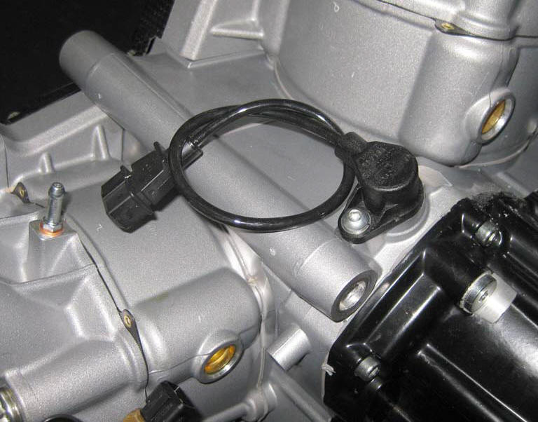
The engine speed-timing sensor is mounted on the flywheel side of the crankshaft. The black aluminium cap on the crankcase covering the hole for checking the air gap with a feeler gauge, is visible on the right.
Location of engine speed-timing sensor connection.
Connection wiring diagram
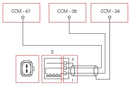
Ccm engine control connection s engine speed-timing sensor, 3 shielding connected to pin 34 of the ecu, black - bk, 1 and 2 electrical terminals of the winding inside the sensor.
In the event of fault
The engine stops (if running) or will not start and the injectors and ignition coils are no longer commanded by the ecu.
Fault codes generated and possible correlated faults
Fault codes generated by the engine control unit and displayed by the dds (pick-up diagnosis):
- Engine speed sensor malfunction (no specific fault indicated by dds): check the integrity of the electric circuit and check that the resistance between pin 1 and pin 2 of the winding is between 774 and 946 ohm at an ambient temperature of 20C.
Warning
Even if the sensor resistance measured is correct, the internal magnet may be damaged, compromising the function of the sensor itself.
Note
Check integrity of electric circuit - short-circuit to vdc = with dashboard on, using a voltmeter, a voltage is measured between the wire tested and ground.
Check integrity of electric circuit - short-circuit to ground = with the battery cables disconnected, using an ohmmeter, continuity is detected between the wire tested and ground.
Check integrity of electric circuit - open circuit = with the battery cables disconnected, using an ohmmeter, no continuity is detected between the two ends of the wire tested.
The dashboard service display shows the error "pick-up" (engine speed sensor) and the eobd warning light activates.
Possible correlated faults: the engine stops (if running) or will not start (the starter motor functions normally) and the ignition coils and injectors are not driven.
Check:
- That the sensor is correctly installed. That the air gap between the sensor and the phonic wheel is 0.6 Mm +/- 0.3 Mm.
- The integrity of the phonic wheel facing the sensor.
If none of the aforementioned tests identify the problem and the engine speed sensor is in proper working order, replace the engine control unit.
Component replacement methods
No special measures are necessary in order to replace the engine speed-timing sensor. Check the air gap between the sensor and one of the teeth of the phonic wheel, inserting a feeler gauge through the hole on the left hand crankcase half (covered by a cap). The air gap must measure 0.6 Mm +/- 0.3 Mm and is non-adjustable.
 Radiator fan relay
Introduction
The radiator fans are powered via a specific relay, which is enabled by the
engine control unit.
Component assembling position
A injection relay; b etv relay (throttle valve actu ...
 Accelerator position sensor (throttle grip)
Introduction
An accelerator position sensor (aps) is mounted on the throttle body of the
diavel, which measures the degree of aperture
of the throttle grip.
The throttle grip is connected to t ...
Other materials:
Removal of the generator cover
Note
This operation is described for an engine removed from the frame since all
reassembly procedures are easier with the
engine on the bench.
Disconnect the connector (a) from the generator cable.
Unscrew the two retaining screws (7) of the centre cap (6) over the end of
the cranksh ...
Removal of the starter motor idler gear
Slide the gear pin (21) complete with the gear (19) and washer (20).
Warning
Pay attention to the washer (20) since it may fall inside the
crankcase half.
At this point, it is possible to remove the starter motor as described in
sect. 6 - 3, Starter motor. ...
Overhaul of the gearbox
Check the condition of the front coupling dogs of the gears. They must be in
perfect condition and with no sign of wear on
the edges of the teeth.
The idler gears must rotate freely on their shafts.
When refitting, make sure the circlips are correctly positioned.
Check the needle roller ...