
Ducati Diavel Service Manual: Exhaust by-pass valve not working correctly
Fault codes
Dds: exvl diagnosis -> position error, potentiometer, short circuit to ground or open circuit (s.C. Gnd or c.O.), Potentiometer short circuited to vdc (potentiometer s.C vdc).
Dashboard: the error "exvl" (exhaust bypass valve) is shown on the service display. The eobd warning light activates.
Wiring diagram
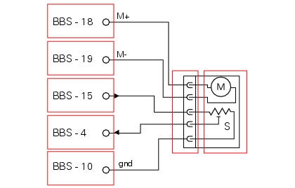
M exhaust bypass valve motor with potentiometer s for position detection, bbs bbs unit connection. 10 Bbs black/blue - bk/b, 15 bbs brown/red - bn/r, 4 bbs yellow/blue - y/b, 18 bbs black/orange - bk/o, 19 bbs black/white - bk/w.
Location of connections and components
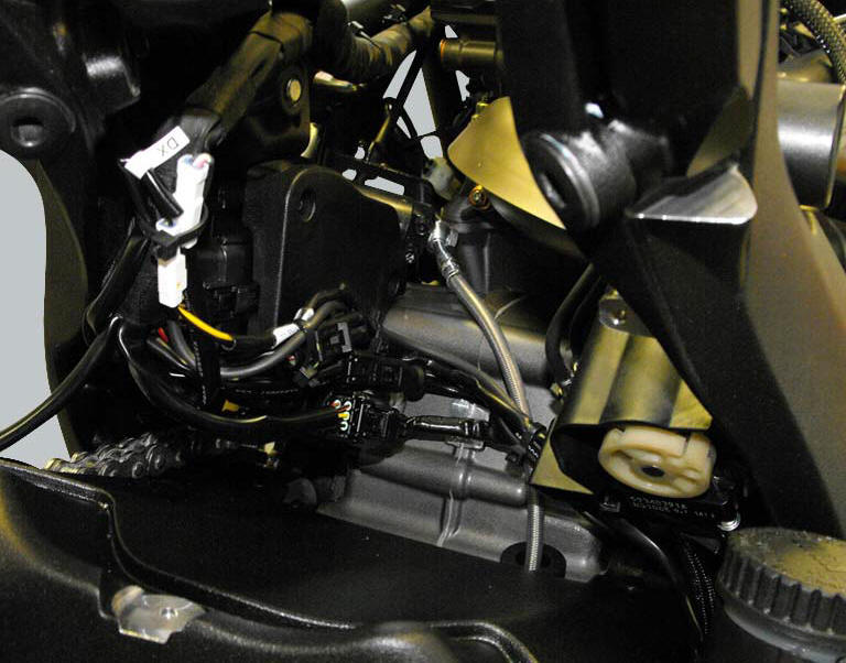
Exhaust bypass valve connection.
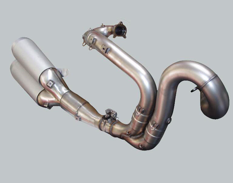
The image shows the exhaust system. The oxygen sensor for the horizontal cylinder (1) is visible on the right, the oxygen sensor for the vertical cylinder (2) is on the left. The catalytic converter is contained within the silencer, while the by-pass valve is installed in the section of pipe connecting the silencer to the twin tailpipes. A metal cable, controlled by an actuator with electric motor and a position sensor, branches off from the exhaust bypass valve.
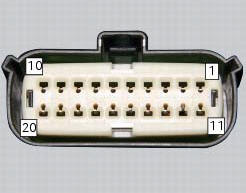
Pin numbering of wiring harness side bbs unit connection
 Stop light not working
Fault codes
Dds: stop light diagnosis -> stop light error (generic stop light malfunction
indication).
Dashboard: the error "stop light" is shown on the service display. The eobd
warning li ...

Other materials:
Reassembly of the connecting rods
Before starting, check that the crankshaft main bearing journals and big-end
journals are free of burrs or evident signs of
machining: if necessary, clean the surfaces with very fine emery cloth and oil.
Check that the grooves are in perfect condition with no signs of forcing.
Clean the cra ...
The immobilizer system
For additional antitheft protection, the motorcycle is
equipped with an immobilizer, an electronic system that
locks the engine automatically whenever the ignition switch
is turned off.
The grip of each ignition key contains an electronic device
that modulates the output signal from a special ...
Clutch cover
Clutch-side crankcase cover
Screw
Screw
Oil level sight glass
Screw
Plate
Bush
Sealing ring
Shim washer
Circlip
O-ring
Locating bush
O-ring
Plug
Sealing washer
Screw
Plug
Panel
Spare parts catalogue
Diavel abs clutch-side crankcase cover
Diavel carbon
a ...