
Ducati Diavel Service Manual: Stop light not working
Fault codes
Dds: stop light diagnosis -> stop light error (generic stop light malfunction indication).
Dashboard: the error "stop light" is shown on the service display. The eobd warning light activates.
Wiring diagram
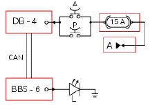
Db dashboard connection, bbs bbs unit connection, a front brake button, p rear brake button, l stop light. A key on power (+15 from hands free relay 30), db 4 grey/red - gr/r, the switch cable connected to a via the fuse is black - bk, bbs 6 grey/red - gr/r, ground on stop light, black - bk.
Location of connections and components
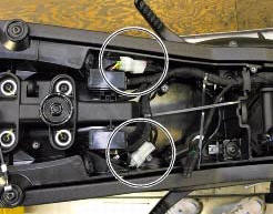
Rear running light and stop light connection.
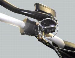
Front brake button mounted near lever operating brake pump.
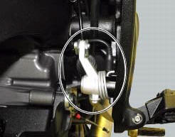
Rear brake button mounted near lever operating brake pump. The button is normally closed (when the brake lever does not press on the button because it has been pressed by enough to cause a braking effect, the contacts close, short circuiting the contacts).
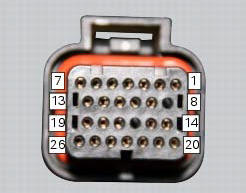
Pin numbering for wiring harness side dashboard connector.
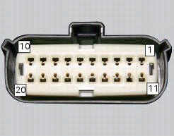
Pin numbering of wiring harness side bbs unit connection.
 Abs disabled information not displayed
Fault codes
Dds: displays a fault code described in the description of the abs system.
Dashboard: no fault code displayed.
Wiring diagram
Checks
The abs fault indicator indicates the occurr ...
 Exhaust by-pass valve not working correctly
Fault codes
Dds: exvl diagnosis -> position error, potentiometer, short circuit to ground
or open circuit (s.C. Gnd or c.O.),
Potentiometer short circuited to vdc (potentiometer s.C vdc).
Da ...
Other materials:
Front wheel
Nut
Washer
Left spacer
Sealing ring
Bearing
Front wheel rim
Inner spacer
Screw
Right spacer
Front wheel shaft
Valve
Spare parts catalogue
Diavel abs front and rear wheels
Diavel carbon
abs
front and rear wheels
Important
Bold reference numbers in this section iden ...
Headlight aim
The motorcycle must be perfectly upright with the tires inflated to the
correct pressure and with a rider seated, perfectly
perpendicular to the longitudinal axis.
Position the motorcycle 10 metres from a wall or a screen.
On the wall or surface, draw a horizontal line at the same height fr ...
Clutch lever button
Introduction
The clutch button is located on the clutch lever. Together with the signal
from the side stand button and the neutral signal
generated by the gear sensor (transmitted to the engine control unit over the
can line), the clutch lever position signal is
used to enable or disable engi ...