
Ducati Diavel Service Manual: The hands free module
Introduction
The hands free module incorporates the control unit communicating with the other nodes on the motorcycle, the on/off button, the microswitches detecting full lock steering angle (for enabling steering lock engagement) and the steering lock.
The module is sealed and its individual components cannot be accessed for diagnosis, repair or replacement.
Wiring diagram
No wiring diagram is available for the components integrated into the hands free module. For the main electric wiring see chapter ("wiring diagram of the hands free system") of this section.
Error codes
"Hands free diagnosis" error: "steering lock": a fault has been detected in
the electric steering lock system. The following
icon appears on the tank dashboard:
- If the error occurred while engaging or disengaging the steering lock, check that the handlebar is fully turned to the left or right and try to engage or disengage the steering lock again.
- If the error occurred while engaging or disengaging the steering lock, check that the lock pin can move freely and is unobstructed, then try to engage or disengage the steering lock again.
- If none of the tests described above identifies the problem, replace the hands free system.
"Hands free diagnosis" error: "eeprom state": fault detected in the internal
hands free system memory. The following
icon appears on the tank dashboard:
- Replace the hands free system
Electrical characteristics and checking component
No electrical characteristics or checking procedures are given for the hands free system as all components are integrated in the module and cannot be accessed for diagnosis, repair or replacement.
The module receives direct 12 volt battery power over pin 1 and via the main 30 a fuse.
Ground is on pin 2.
In the event of fault
In the event of any hands free system fault, the engine may switch off or engine start may not be possible.
In the event of a fault in the steering lock integrated into the hands free system occurring during either engagement or disengagement, the system will attempt to automatically retract the lock pin. If this fails, a low volume alarm signal is emitted by the hands free system.
Installation location
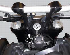
The plastic shield covering the hands free system is visible in the photo
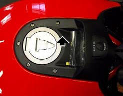
The hands free system on/off button is shown in the photo, with the plastic shield removed.
The lock pin of the electric steering lock is visible in the lower portion of the hands free system.
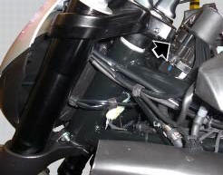
The photo shows the hands free system removed from the motorcycle fuel tank. One of the two switches detecting the full lock handlebar steering position is indicated in the photo.
Component replacement methods
No special measures or reprogramming are necessary in order to replace the hands free system. However, the motorcycle keys must be reprogrammed after replacement. See chapter "programming/reprogramming keys"
 Wiring diagram of the hands free system
The diagram illustrates the inputs, outputs and communication lines used by
the hands free system.
1I - on/off button placed on the hands free system (located below the plastic
cover)
2I - o ...
 Communication antenna
Introduction
The communication antenna enables the hands free system to detect and
communicate with the active or passive key.
The active key is detectable within a range of 1.5 Metres, whereas ...
Other materials:
Lap activation/deactivation function (lap time)
This function activates and deactivates the lap function (lap time).
To access the function it is necessary to view the ""setting" menu", using
buttons (1) "s" or (2) "t" select the "lap"
function and press the reset button (3) to enter the following page.
Function state is highlighted on t ...
Tips for use on the track
We recommend level 8 be used for a couple of full laps (to
allow the tyres to warm up) in order to get used to the
system. Then try levels 7, 6, etc., In succession until you
identify the dtc intervention level that suits you best (always
try each level for at least two laps to allow the tyres t ...
Abs system operating information
The response of the system is based on the analysis of the speed signals for
front and rear wheels; the system is
automatically deactivated if either of these signals is missing.
Note
In the event of the abs control unit detecting a fault in the abs
electronic management system, it activates ...