
Ducati Diavel Service Manual: Headlight aim
The motorcycle must be perfectly upright with the tires inflated to the correct pressure and with a rider seated, perfectly perpendicular to the longitudinal axis.
Position the motorcycle 10 metres from a wall or a screen.
On the wall or surface, draw a horizontal line at the same height from the ground as the centre of the headlight and a vertical line aligned with the longitudinal axis of the motorcycle.
Note
If possible, perform this check in conditions of low ambient light.
Switch on the low beam. The height of the upper limit between the dark area and the lit area must not be more than nine tenths of the height of the centre of the headlight from the ground.
Note
This is the procedure specified by italian regulations for checking the maximum height of the light beam.
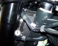
The vertical alignment of the headlamp can be adjusted manually by turning screw (1).
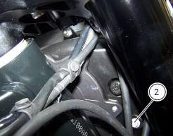
Turn the screw (2) to set beam height.
 Changing bulbs
Changing the headlight bulbs
Before replacing a burnt out light bulb, ensure that the replacement bulb has
the same voltage and power rating as
specified for the lighting device in question (sect. ...
 Indicating devices
Checking the indicating devices
In the event of a fault, the internal connections of the device must be
checked in all operating conditions. To do this, it is
necessary to disconnect the switch co ...
Other materials:
Hands free key (hf) not recognised
The activation of this (amber yellow) "warning" indicates
that the hands free system does not detect the active key
(1, fig. 62) Near the vehicle.
Note
In this case, ducati recommends checking that the
active key (1, fig. 62) Is near the vehicle (and has not been
lost) and that it f ...
Stop light not working
Fault codes
Dds: stop light diagnosis -> stop light error (generic stop light malfunction
indication).
Dashboard: the error "stop light" is shown on the service display. The eobd
warning light activates.
Wiring diagram
Db dashboard connection, bbs bbs unit connection, a front brake ...
Side stand button
Introduction
The side stand button is located on the side stand. Together with the signal
from the clutch button and the neutral signal
generated by the gear sensor (transmitted to the engine control unit over the
can line), the side stand position signal is
used to enable or disable engine s ...