
Ducati Diavel Service Manual: Indicating devices
Checking the indicating devices
In the event of a fault, the internal connections of the device must be checked in all operating conditions. To do this, it is necessary to disconnect the switch connector from the main wiring harness (sect. 6 - 1, Routing of wiring on frame).
Then analyse the switch using an analogue or digital multimeter (sect. 6 - 11, Using a multimeter to check the electrical systems).
Note
The same test may be carried out using the "dds" tester (sect. 6 - 11, Diagnostic instruments).
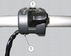
Checking the left-hand handlebar switch
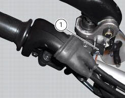
To remove the left-hand handlebar switch, undo the fixing screws (1) and disconnect it from the electric system.

The colours mentioned in the following descriptions refer to the colours of the wires from the switch and not to the colours of the wires of the main electric system.
Horn button
Connect the terminals of a multimeter to the blue/white and brown cables to check for electrical continuity, which must be available when horn is pressed (see sect. 6 - 11, "Using a multimeter to check the electrical systems", related to multimeter operation). When horn button is pressed, resistance value taken by the multimeter should be close to zero and, if available, a continuity beep should be heard. When the horn button is not pressed, the resistance value should be infinity (there is no continuity as the electrical contacts inside the pushbutton are open) and no continuity beep should be heard. If these conditions are not met, the device must be replaced.
Turn signal switch (turn)
Connect the multimeter to the grey and brown cables arriving from the turn signal switch and check for electrical continuity when operating the right turn indicator (see sect. 6 - 11, "Using a multimeter to check the electrical systems", related to operation of the multimeter). Repeat the above procedure for the right turn signal, but connect the multimeter to the (orange and grey) wires.
Low and high beam headlights (dimmer)
Test using the same procedure, applying the probes of the meter to the cables: (red/blue and light blue/yellow).
Control switch (mode)
Connect the multimeter to the brown and blue/yellow cables arriving from the function selector switch and check that when operating the pushbutton in the (s) position there is electrical continuity (sect. 6 - 11, "Using a multimeter to check the electrical systems", related to operation of the multimeter). Repeat the same procedure, operating the push button in the (t) position, connecting the multimeter to the blue/yellow and orange cables.
Flasher (passing) check for continuity between the red/blue and brown cables.
Refit the lh switch tightening the screws (1) to a torque of 1.3 Nm +/- 10% (sect. 3 - 3, Frame torque settings).
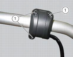
Checking the right-hand handlebar switch
To remove the right-hand handlebar switch, undo the retaining screws (1) and disconnect the wiring connector from the electric system.
The colours mentioned in the following descriptions refer to the colours of the wires from the switch and not to the colours of the wires of the main electric system.
Engine stop button
Using a multimeter, check for electrical continuity across the red/white and red/black cables (see sect. 6 - 11, Using a multimeter to check the electrical systems, related to the multimeter operation). When the switch is in the run position, there should be electrical continuity between the two wires. When the switch is in the off position there should be no electrical continuity between the two wires.
If these conditions are not met, the engine stop switch is not working correctly and must be renewed.
Starter button
Proceed as described for the engine stop button and check for electrical continuity across the blue/white and black cables when the starter button is pressed (see sect. 6 - 11, Using a multimeter to check the electrical systems related to the multimeter operation). If there is no continuity, the starter switch is defective and must be renewed.
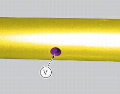
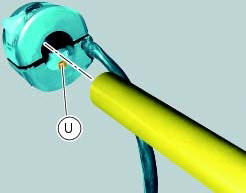
Refit the rh switch inserting the switch pin (u) into the hole (v) in the handlebar and tightening the screws (1) to a torque of 1.3 Nm +/- 10% (sect. 3 - 3, Frame torque settings).

Checking the front and rear brake light switches, neutral light switch, oil pressure switch and clutch switch
Brake light switches
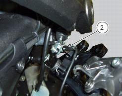
To check the operation of the front (1) and rear (2) stop lights use a multimeter to check that when the front or rear brake is pressed, there is electrical continuity (pos. A) across the terminals of the corresponding switch (sect. 6 - 11, Using a multimeter to check the electrical systems, related to the multimeter operation). When the brake is released, there must be no electrical continuity across the terminals of the corresponding switch (pos. B). If these tests fail to produce positive results, the part in question must be renewed.
Gear selector sensor warning light to check the gear selector warning light switch (3) proceed as follows.
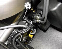
The neutral light does not illuminate on the dashboard.
Remove the electric terminal connected to the neutral switch. Switch on the ignition switch (ignition key to on position) and ensure that the light illuminates when the terminal is earthed. If the light switches on, the neutral light switch should be changed. If the light stays off, switch off the ignition (ignition key set to off) to switch off the dashboard and check for electrical continuity between the neutral switch and engine ecu with a multimeter.
The neutral light on the dashboard is permanently illuminated.
Switch on the ignition (ignition key set to on) and remove the electrical terminal from the neutral switch. If the light turns off, the neutral switch should be changed. If the light stays off, switch off the ignition (ignition key set to off) and use a multimeter to check whether the section of circuit between neutral switch and engine ecu is earthed.
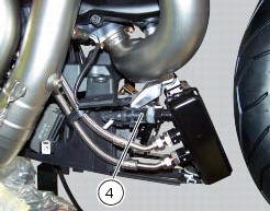
Oil pressure sensor
To test the operation of the engine oil pressure sensor (4), proceed as follows.
Use the dds to check that oil pressure into the engine lubrication circuit complies with the specified values (sect. 6 - 11, Check the engine oil pressure).
If the engine oil pressure value is outside the specified range, check the oil circuit components and service as necessary.
If engine oil pressure value is within the specified range and the oil pressure warning light on the dashboard stays off, switch on the dashboard (ignition key set to on) without starting the engine, and disconnect the electrical terminal from the pressure sensor and connect it to earth. If the warning light now illuminates, this means the sensor is defective and must be replaced. If the warning light does not illuminate, use a multimeter and check for electrical continuity in the section of the circuit between sensor and warning light on the dashboard (this check must be performed with the ignition key set to off, i.E. With dashboard off).
If the engine oil pressure complies with the stated values and the engine oil pressure warning light on the dashboard is continuously illuminated, switch on the dashboard (ignition key set to on) and start the engine, then disconnect the electrical terminal normally inserted on the pressure sensor. If the warning light now switches off, this means the sensor is defective. If the warning light does not switch off, use a multimeter to check that the section of the circuit between sensor and warning light on the dashboard is not connected to earth (this check must be performed with the ignition key set to off, i.E. Dashboard off).
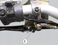
Clutch switch
For the clutch switch (5) proceed in the same manner as for the brake light switches (see beginning of this paragraph).
 Headlight aim
The motorcycle must be perfectly upright with the tires inflated to the
correct pressure and with a rider seated, perfectly
perpendicular to the longitudinal axis.
Position the motorcycle 10 met ...

Other materials:
"Parking" function
This function activates the "parkin"h mode.
The "parkin"h function activates the front and rear parking
lights when the vehicle is turned off so it is visible when
parked.
The function is activated by pressing the button (2, fig. 14)
?"´" for 3 seconds du ...
Removal of the fuel tank
On the usa version remove the canister filter as indicated in sect. 8 - 10,
"Removal of the evaporative emissions
canister".
Loosen and remove the front retaining screw (4)
Remove the flange cover (a) by loosening the screws (b), disconnect the
quick-release fittings (c) from the fl ...
Fuel pressure test
Note
The on-screen icons used during this procedure are explained in a table at
the end of this section.
Undo the screws (2) and remove the flange cover (1).
Remove one of the two pipes of the fuel system (3).
Use the fuel pressure pipe (4) part no. 590.1.189.1A by connecting one e ...