
Ducati Diavel Service Manual: Shimming the shafts
Before assembling the crankcase halves, calculate the shims required to obtain the correct end float of the crankshaft and gearbox shafts.
To determine the correct shim thickness proceed as follows.
Shimming the crankshaft
- After having installed the new main bearings (with bushing (a) or flanged bearings (b)) proceed as follows to determine the total "sa" height of the shimming:
- Measure the distance "la" between the bearing contact surfaces on the crankshaft;
- Measure the depths "la1" and "la2" corresponding to the distance between contact surface of the crankcase half and the contact surface of the inner race of the bearings.
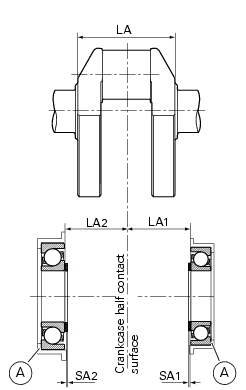
Add 0.30 Mm preload for crankshaft axial bearings to bed in correctly into their seats (inner rings seated inside outer ring).
Thus, we obtain: sa=la1+la2+0.30-La.
To calculate the thickness of each shim note that: sa=sa1+sa2 where "sa1" and "sa2" represent the shims for the clutch-side crankcase half 1 and the alternator-side crankcase half 2.
Considering the alignment of the shaft, this gives: sa1=la1+0.15-La/2; and finally, the second shim thickness: sa2=sa-sa1.
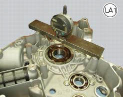
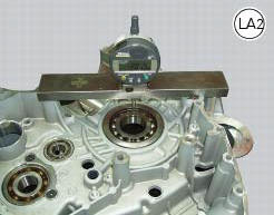
In addition to the above procedure, the following is a practical shimming method, providing a guide on how to calculate the crankshaft shim thickness accurately.
Install a shim of minimum thickness (1.90 Mm) on each side of the crankshaft to prevent contact between the crankshaft web and the crankcase.
Install the crankshaft and assemble the two crankcase halves.
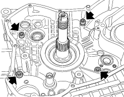
Fit four m8 screws in the seats indicated in figure and tighten them to a torque of 19 nm (min. 17 Nm - max. 21 Nm) (sect. 3 - 3, Engine torque settings).
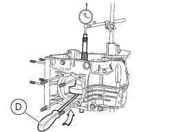
Place a dial gauge (c) with magnetic base on a support plate fixed to crankcase.
Bring the stylus into contact with the end of the crankshaft and set the dial gauge to zero in this position.
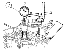
Place a lever (d) between crankcase and crank web of the crankshaft pushing towards dial gauge.
Note on the dial gauge the total clearance and add a preload of (0.30 Mm) plus the thickness of the shims used (1.90X2=3.8 Mm).
Divide the resulting value by two to obtain the thickness of the shim packs to be installed at either end of the crankshaft.
Note
After assembling the crankcase halves, the crankshaft should turn with some interference in the new bearings.
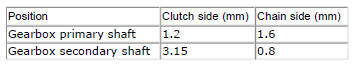
Shimming the gearbox shafts
The following thickness spacers are supplied as spare parts.
Shimming the gearbox selector drum
The following thickness spacers are supplied as spare parts.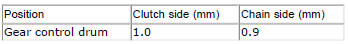
 Reassembly of the crankcase halves
The crankcase halves must be in good condition and perfectly clean. The
mating surfaces must be perfectly flat and free
from burrs.
Overhauling the alternator-side crankcase half
The following pa ...
 Reassembly of the crankcase halves
If removed, apply threadlocker on the screw (36), insert it with the washer
(37) on the crankcase half and tighten it to The torque of 8 nm
(min. 7 Nm - max. 9 Nm) (sect. 3 - 3, Engine torque sett ...
Other materials:
Removal of the tool tray
To remove the tool tray unit from the lateral footrests, loosen the screws
(40) and remove the splashguard (20).
Undo the screws (15) and remove the cover (16).
Move the wiring branch from the seat (s) on the tool tray.
Loosen the screws (24) to remove the tool tray unit (23) from ...
Refitting the lubrication system
Note
Before fitting the pipes (7), it is recommended to check the presence of
the o-rings (e). Lubricate them by using engine
oil.
If the nipples (5) have been removed from the radiator insert a washer (6) on
each nipple (5) and apply specific
threadlocker on threads on the radiator side ...
Lubricating cables and joints
Check the outer sheath of the throttle control and cold start
lever cables for damage at regular intervals. The outer plastic
cover should not be flattened or cracked. Operate the
controls to make sure the inner cables slide smoothly inside
the outer sheath: if you feel any friction or catching, ...