
Ducati Diavel Service Manual: High beam lights not working
Fault codes
The hi beam light on the (slave) dashboard flashes at 1hz frequency.
Wiring diagram
Location of elements on motorcycle
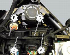
(A) injection relay; (b) etv relay (throttle valve operating engine); (c) radiator fan relay; (d) hands free relay.
Fuses located at the rear left of the vehicle.
(1) 10A dashboard; (2) 5a engine control unit; (3) 15a key-sense; (4) 20a injection relay; (5) 10a throttle opening relay (etv).
Fuses located at the rear right of the vehicle.
(1) 7.5A black box system (bbs); (2) 7.5A navigator/alarm; (3) 25a abs 2; (4) 30a abs 1; (5) 10a fans; (6) 7.5A diagnosis/recharge.
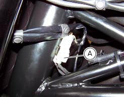
(A) low / high beam and parking light connections
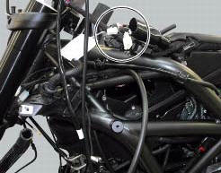
Location of left hand handlebar switchgear set connection.
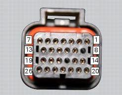
Pin numbering for wiring harness side dashboard connector.
Note
Check integrity of electric circuit - short-circuit to vdc = with dashboard on, using a voltmeter, a voltage is measured between the wire tested and ground.
Check integrity of electric circuit - short-circuit to ground = with the battery cables disconnected, using an ohmmeter, continuity is detected between the wire tested and ground.
Check integrity of electric circuit - open circuit = with the battery cables disconnected, using an ohmmeter, no continuity is detected between the two ends of the wire tested.

 Low beam lights not working
Location of connections and components
(A) injection relay; (b) etv relay (throttle valve operating engine); (c)
radiator fan relay; (d) hands free relay.
Fuses located at the rear left of ...
Other materials:
Rear shock absorber assembly
Special screw
Screw
Nut
Grub screw
Bush (right)
Bush (left)
Screw
Sealing ring
Roller bearing
Linkage (left)
Shock absorber (rear)
Linkage (right)
Spacer
Special screw
Screw
Bush
Ball joint
Rocker arm assembly
Support
Washer
Nut
Screw
Shock absorber ...
Riding style function (riding style change)
This function changes the motorcycle riding style.
Each riding style is associated with a different intervention level of the
traction control (dtc - ducati traction control) and
different engine power and output.
To change the motorcycle riding mode, press the reset button once
(3) and th ...
Refitting the cylinder heads pulleys/fixed tensioners
Check that the keyway on the end of the camshaft is in good condition and
without burrs.
Fit a woodruff key (b) in the keyway of each camshaft.
Fit the pulley (11) on the camshaft, inserting the woodruff key in the in the
slot (c) in the pulley.
Apply the recommended grease to the t ...